Inverted quantifiable container

A technology for containers and container mouths, which is applied in the direction of bottle/container caps, caps, caps, etc., which can solve problems such as large quantitative errors, unusable, rolling beads stuck and blocked, etc., to achieve smooth and efficient use convenient effect

Pending Publication Date: 2019-05-24
ZHONGSHAN HUABAOLE DAILY NECESSITIES IND CO LTD
View PDF0 Cites 1 Cited by
  • Summary
  • Abstract
  • Description
  • Claims
  • Application Information

AI Technical Summary

Problems solved by technology

[0002] There are many types and structures of containers that can be quantified. Among them, for the quantitative container that is used upside down with the built-in rolling ball, the rolling ball generally moves up and down. In the prior art, when the original inverted quantitative container completes the quantitative and then pours out the liquid, The liquid in the container is likely to continue to enter the dosing chamber, resulting in large or inaccurate dosing errors; at the same time, when the dosing container is turned upside down so that the liquid in the container enters the dosing chamber, the rolling beads will be stuck and blocked in the dosing chamber. on the liquid port, so that the quantification cannot be carried out smoothly, and thus it cannot be used

Method used


Image

  • Inverted quantifiable container
  • Inverted quantifiable container
  • Inverted quantifiable container

Examples


Embodiment 1

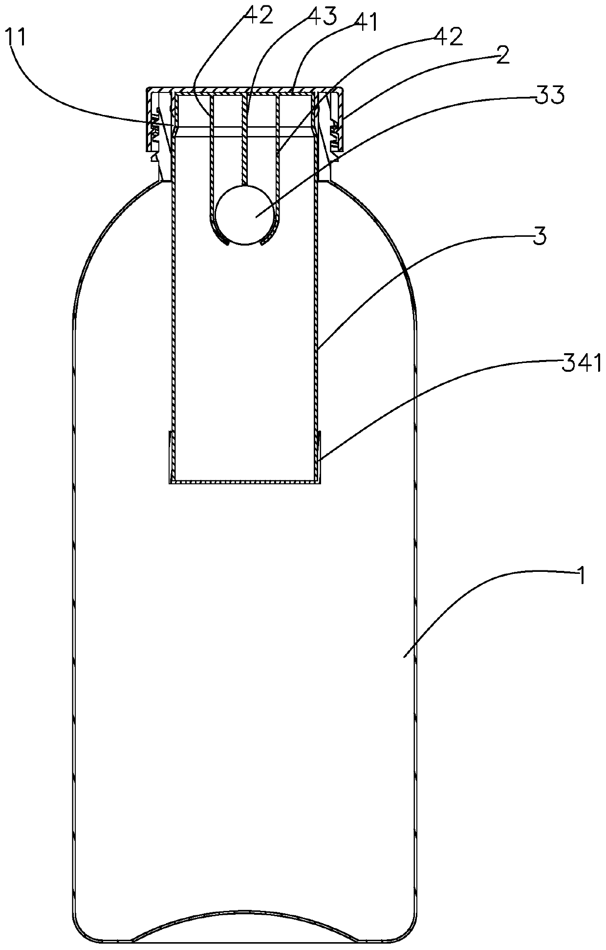
[0036] In Embodiment 1, the cover 2 is connected to the mouth 11 of the container through threads, and the cover 2 can also be integrally connected to the container body 1 through a connecting belt to be reversibly fastened to the mouth 11 of the container.

[0037] When using Example 1, the container body is tilted against the liquid outlet side, and the rolling ball is separated from the liquid inlet to open the liquid inlet. At this time, the liquid in the inner cavity of the container body enters the liquid storage cylinder through the liquid inlet hole Inside, when the liquid in the liquid storage cylinder meets the usage amount, stand the container upright, open the cover, and then tilt the container body to the side with the liquid outlet, and the rolling ball will be under the action of gravity and the guide limit structure And the liquid inlet is blocked, and now the inner cavity of the container body and the inner cavity of the liquid storage cylinder are isolated fro...
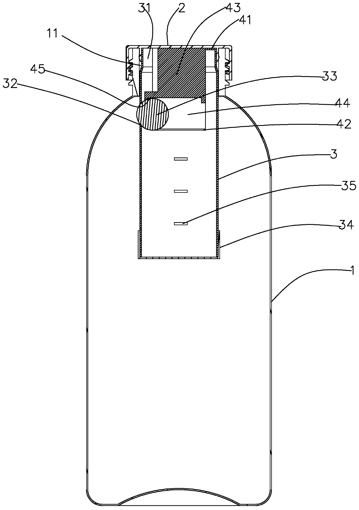
Embodiment 2

[0040] In Embodiment 2, the cover 2 is screwed to the container mouth 11 , and the cover 2 can also be fastened to the container mouth 11 as required.

[0041] The usage principle of embodiment 2 is the same as that of embodiment 1.
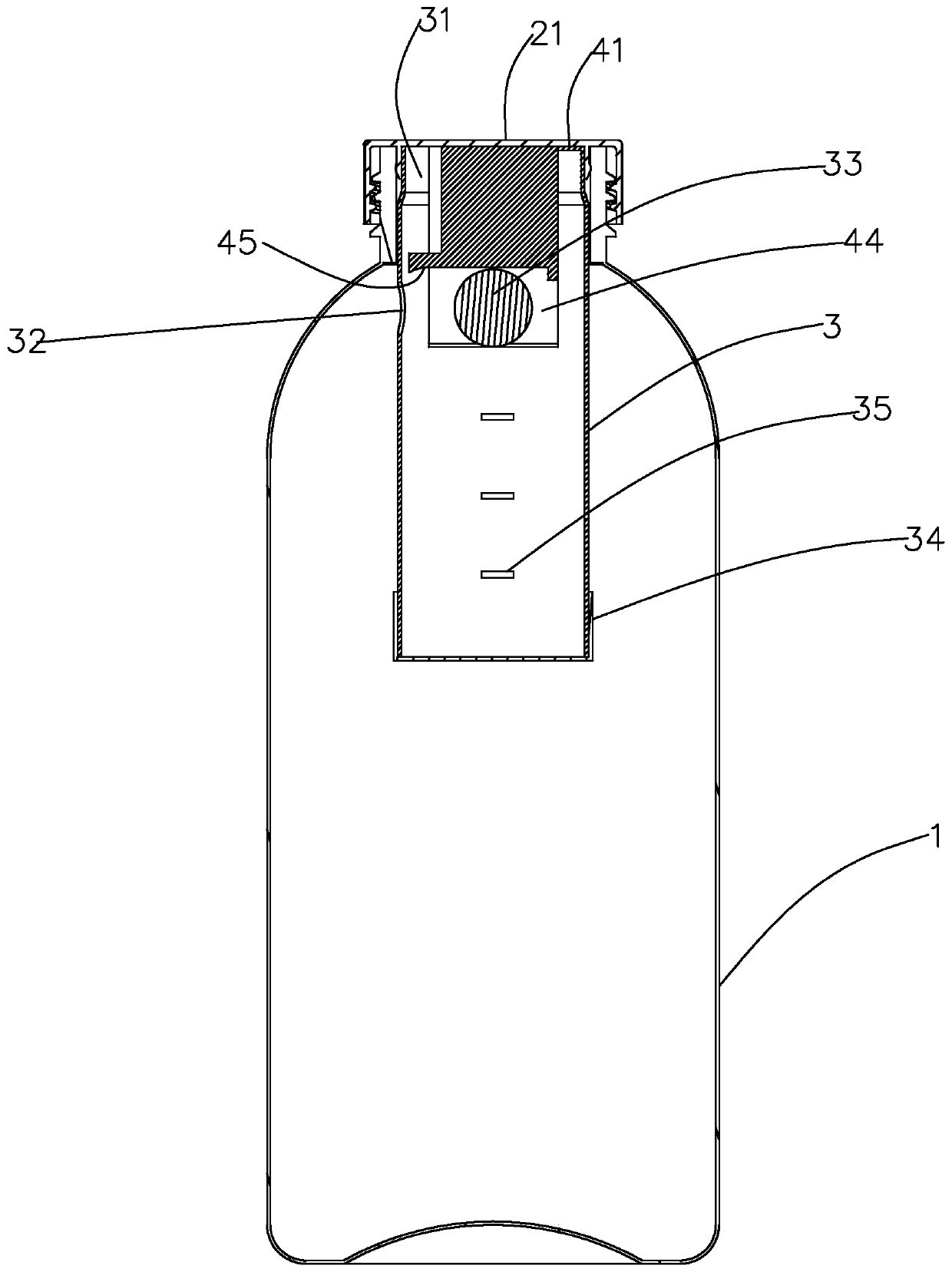
Embodiment 3

[0043] The working principle of embodiment 3 is the same as that of embodiment 1. In Embodiment 1, the cover 2 is connected to the upper mouth of the connection base 12 through threads; if necessary, the cover 2 can also be integrally connected to the connection base 12 through a connection belt and reversibly fastened to the connection base 12. Base 12 upper mouth.

[0044] Such as Figure 11-12 As shown, as a specific embodiment 4 of the present invention, the difference from embodiment 3 lies in the structure and connection method of the cover and the connection base, that is, the cover 2 is rotatably fastened to the upper mouth of the connection base 12, so The side of the cover 2 is provided with a liquid discharge notch 21, and the side of the upper mouth of the connection base 12 is provided with a fixed liquid discharge notch 121. When the cover 2 is rotated relative to the connection base 12, the liquid discharge notch 21 can be moved. Align with the liquid outlet g...


PUM


Abstract

The invention discloses an inverted quantifiable container, which comprises a container body. The container body is provided with a container opening, the container opening is directly or indirectly connected with a sealing cover, a liquid storage cylinder is fixed to the position, relative to the container body, in the container body, the lower end of the liquid storage cylinder is sealed, a liquid outlet communicating with an inner cavity of the liquid storage cylinder is formed in the upper end of the liquid storage cylinder, a liquid inlet is formed in the side face of the liquid storage cylinder, the liquid inlet and the liquid outlet are located in the same side, the liquid storage cylinder is internally and movably provided with a rolling bead capable of plugging the liquid inlet, and further comprises a guiding and limiting structure used for guiding and limiting the rolling bead to enable the rolling bead to plug the liquid inlet, the rolling bead is arranged in the guiding and limiting structure, when the container body is inclined, the rolling bead can move correspondingly in the transverse direction relative to the container body, and thus the liquid inlet can be openedor plugged. The inverted quantifiable container has the characteristics that moving is flexible, quantifying is facilitated, and the quantitative liquid is taken in an inverted mode.

Description

【Technical field】 [0001] The present invention relates to a container, especially a reversible quantitative container. 【Background technique】 [0002] There are many types and structures of containers that can be quantified. Among them, for the quantitative container that is used upside down with the built-in rolling ball, the rolling ball generally moves up and down. In the prior art, when the original inverted quantitative container completes the quantitative and then pours out the liquid, The liquid in the container is likely to continue to enter the dosing chamber, resulting in large or inaccurate dosing errors; at the same time, when the dosing container is turned upside down so that the liquid in the container enters the dosing chamber, the rolling beads will be stuck and blocked in the dosing chamber. On the liquid port, the quantification cannot be carried out smoothly, and then it cannot be used. [0003] In view of above-mentioned technical problem, the present in...

Claims


Application Information

Patent Timeline
IPC IPC(8): B65D83/00B65D41/04B65D25/02
Inventor 李红彪
Owner ZHONGSHAN HUABAOLE DAILY NECESSITIES IND CO LTD
Why Eureka
Try Eureka