Clutch state locking structure of rotary control clutch

A locking structure and clutch technology, applied in the field of clutches, can solve problems such as user obstacles, user injuries, and inability to guarantee stability, and achieve the effect of smooth use and easy installation and operation.

Pending Publication Date: 2019-08-02
HANGZHOU SUKONG SOFTWARE CO LTD
View PDF1 Cites 1 Cited by
  • Summary
  • Abstract
  • Description
  • Claims
  • Application Information

AI Technical Summary

Problems solved by technology

[0004] This utility model is applied to the clutch device between the wheel core and the pulley, which can realize the transmission connection or mutual disengagement between the wheel core and the pulley according to the needs, but the clutch device cannot guarantee the stability of these two states, that is, during use In the process, due to some accidental external factors, it is easy to switch between the two states of transmission connection and mutual disengagement between the wheel core and the pulley, which will bring obstacles to the user and even cause harm to the user.

Method used


Image

  • Clutch state locking structure of rotary control clutch
  • Clutch state locking structure of rotary control clutch
  • Clutch state locking structure of rotary control clutch

Examples


Embodiment Construction

[0025] The present invention will be described in further detail below in conjunction with the accompanying drawings and specific embodiments.

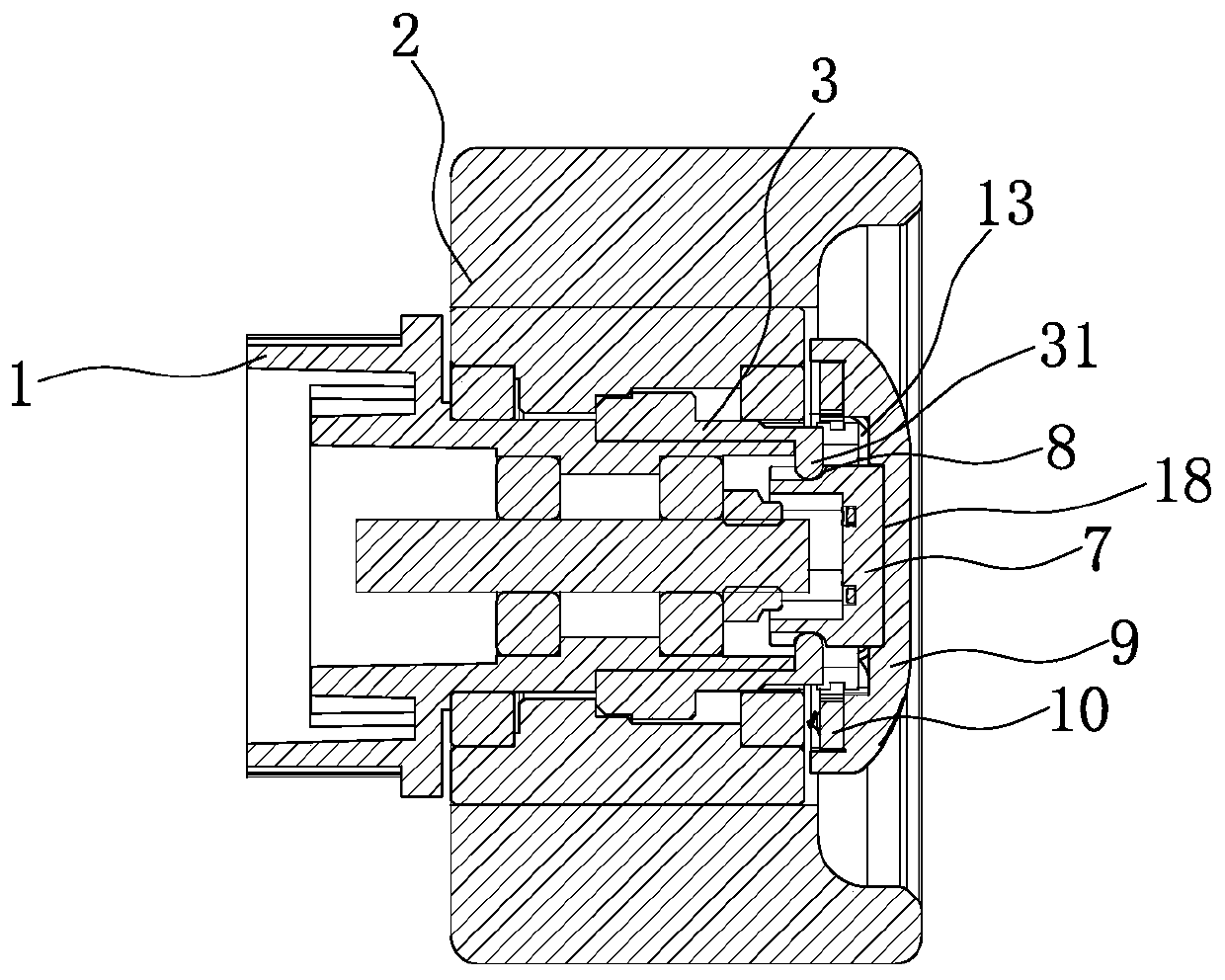
[0026] Such as figure 1 As shown, a clutch state locking structure of a rotary clutch, the rotary clutch includes a clutch part 3 arranged between the driving rotary part 1 and the driven rotary part 2, and the clutch part 3 is connected with a clutch control rotary body 7 and when the clutch control rotating body 7 rotates, the active rotating member 1 and the driven rotating member 2 can be circumferentially positioned or separated in the circumferential direction. The clutch controlling rotating body 7 is provided with a The elastic non-return structure that can prevent the rotation of the clutch control rotating body 7.

[0027] A clutch 3 is provided between the active rotating part 1 and the driven rotating part 2, and the clutch 3 can make the driving rotating part 1 and the driven rotating part 2 be connected (circumferential...


PUM


Abstract

The invention belongs to the technical field of clutches, and particularly relates to a clutch state locking structure of a rotary control clutch. The rotary control clutch comprises a clutch part arranged between a driving rotating part and a driven rotating part, and the clutch part is connected with a clutch control rotating body. After the clutch control rotating body rotates, the driving rotating part and the driven rotating part can be positioned or separated in the circumferential direction, and the clutch control rotating body is provided with an elastic non-return structure capable ofpreventing the clutch control rotating body from rotating back after the clutch control rotating body is rotated. According to the structure, the elastic non-return structure is arranged between thetwo rotating parts, so that it is ensured that the states of the two rotating parts can be kept stable when the two rotating parts are in a transmission connection state or a separated state, the situation that switching between the two states is easily caused due to some occasional external factors is avoided, the use smoothness of a product with a clutch mechanism is ensured, and the accident that a user is injured is prevented.

Description

technical field [0001] The invention belongs to the technical field of clutches, in particular to a clutch state locking structure of a rotary clutch. Background technique [0002] The clutch mechanism is a commonly used structure in the mechanical transmission process, which can selectively realize the transmission connection or mutual separation between two different parts, so as to meet the different needs of users in different usage scenarios. [0003] For example, a Chinese utility model patent discloses a driving wheel for an electric scooter [application number: 201720468425.4]. The utility model patent includes a tire, a wheel core and a pulley on one side of the wheel core. A clutch device is provided between the pulleys, and the clutch device can drive the wheel core to be connected or separated from the pulley. The clutch device includes an end gear. The top half cylinder; the left side of the pulley is provided with slopes corresponding to the inclined top surfa...

Claims


Application Information

Patent Timeline
IPC IPC(8): F16D11/14F16D23/12
CPCF16D11/14F16D23/12
Inventor 朱筱凯
Owner HANGZHOU SUKONG SOFTWARE CO LTD
Why Eureka
Try Eureka