
Automatic glue dispensing device of guide rail boxing machine and using method

A technology of automatic glue dispensing and cartoning machine, which is applied to devices and coatings that apply liquid to the surface. Dispensing uniform effect

Active Publication Date: 2021-08-17
河源市万利科技有限公司
View PDF6 Cites 0 Cited by
  • Summary
  • Abstract
  • Description
  • Claims
  • Application Information

AI Technical Summary

Problems solved by technology

[0004] The purpose of the present invention is to solve the problem that the dispensing device in the prior art often needs to indirectly stop the transmission device when it is in use, which will easily reduce the service life of the

Method used


Image

  • Automatic glue dispensing device of guide rail boxing machine and using method
  • Automatic glue dispensing device of guide rail boxing machine and using method
  • Automatic glue dispensing device of guide rail boxing machine and using method

Examples


Example Embodiment

[0030] Example one

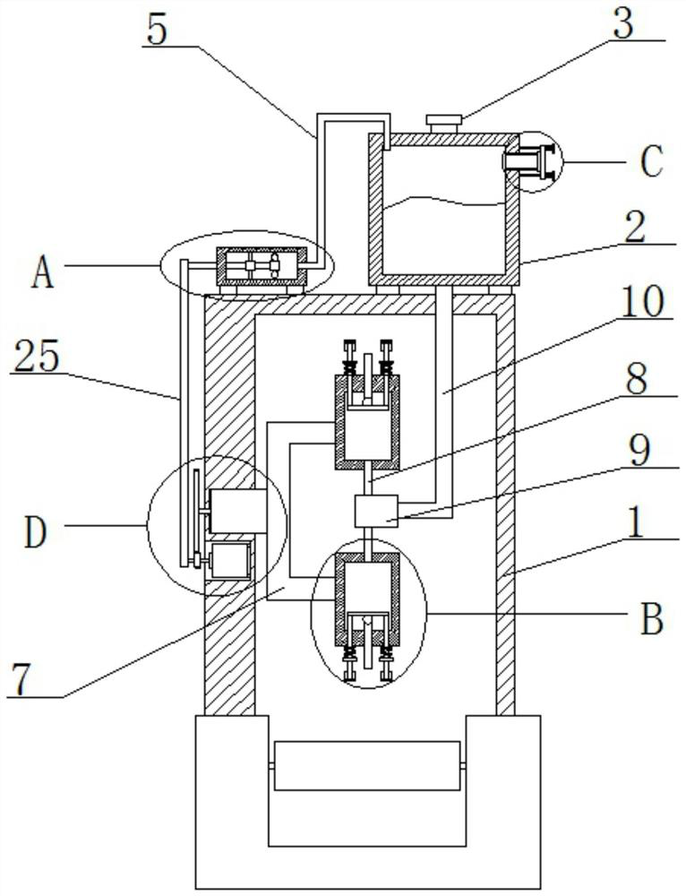
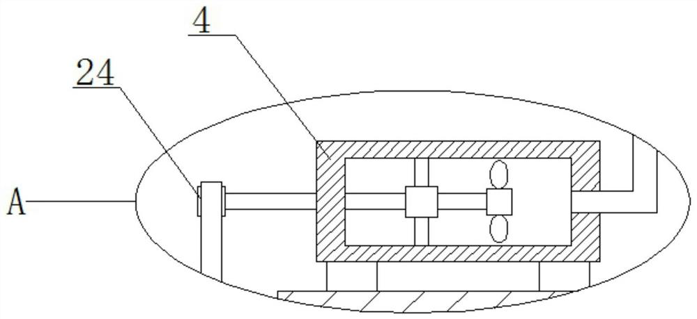
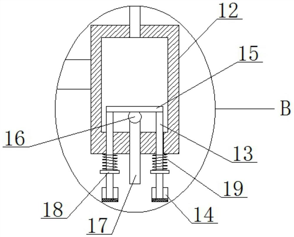
[0031] Refer Figure 1-5 The automatic dispensing device of a guide rail box includes a housing 1, and a reservoir 2 is fixedly coupled to the top of the housing 1, and a top cover 3 is provided with a top cover 3, and a pneumatic pressure is fixed to the top of the housing 1. The pump 4, one side of the air pressure pump 4 is connected to the air pressure pipe 5, and one end of the air pressure pipe 5 is connected to the top of the storage case 2, and the inner wall of the casing 1 is opened, and the rotary groove is rotated, and the rotary groove is rotated and mounted with the rotary shaft 6. One end of the rotating shaft 6 is fixedly connected to the connecting frame 7, and there is a plurality of dispensing mechanisms on the connecting frame 7, and the plurality of dispensing mechanisms are connected to the adhesive tube 8, and the plurality of adhesive tubes 8 are connected to the same connection. The tube 9, the bottom of the storage case 2 is connected ...

Example Embodiment

[0038] Example 2

[0039] Refer Figure 1-5 The automatic dispensing device of a guide rail box includes a housing 1, and the top portion of the housing 1 is secured by welding, and the top cover 3 is provided with a top cover 3, and the top of the housing 1 is passed through the bolt. The air pressure pump 4 is fixedly connected, and the air pressure pipe 5 is connected to the side of the air pressure pump 4, and one end of the air pressure pipe 5 is connected to the top of the storage case 2, and the inner wall of the casing 1 has a rotary groove, rotating in the rotary groove. There is a rotating shaft 6, one end of the rotating shaft 6 is fixedly coupled with a connecting frame 7 by welding, and a plurality of dispensing mechanisms are fixed to the connecting frame 7, and the plurality of dispensing mechanisms are connected to the adhesive tube 8, and the plurality of adhesive tubes 8 are connected. The same connecting tube 9 is connected, and the bottom of the storage case 2 i...


PUM


Abstract

The invention belongs to the field of glue dispensing devices, particularly relates to an automatic glue dispensing device of a guide rail boxing machine and a use method, and aims to solve the problems that the service life of a motor of a conveying device is easily shortened due to the fact that the conveying device often needs to be indirectly stopped when an existing glue dispensing device is used, and because glue has certain viscosity, unsmooth glue discharging easily appears. According to the technical scheme, the automatic glue dispensing device comprises a shell, wherein the top of the shell is fixedly connected with a storage box, a top cover is arranged at the top of the storage box, the top of the shell is fixedly connected with a pneumatic pump, one side of the pneumatic pump is connected with a pneumatic pipe, one end of the pneumatic pipe is connected with the top of the storage box, and a rotating groove is formed in the inner wall of one side of the shell. During use, a conveying device does not need to be indirectly stopped, use is smooth, the efficiency is higher, the service life of a motor is prolonged, and by controlling air pressure in the storage box, glue discharging is smooth, and glue dispensing is more uniform.

Description

technical field [0001] The invention relates to the technical field of glue dispensing devices, in particular to an automatic glue dispensing device of a rail cartoning machine and a method for using it. Background technique [0002] The guide rail cartoning machine is a machine that automatically sets the carton on the guide rail to facilitate product transportation and increase the appearance of the product. The guide rail cartoning machine is mainly divided into two parts: folding box and gluing. For the gluing part, now Some cartoning machines mostly use equipment such as automatic glue spraying heads, which are very expensive and difficult to maintain; [0003] The existing glue dispensing device often needs to indirectly stop the conveying device during use, which easily reduces the service life of the motor of the conveying device, and because the glue has a certain viscosity, it is prone to poor glue discharge. Contents of the invention [0004] The purpose of the...

Claims


Application Information

Patent Timeline
IPC IPC(8): B05C5/02B05C11/10B05C13/02
CPCB05C5/0208B05C11/1002B05C13/02
Inventor 谢阳海吴跃进
Owner 河源市万利科技有限公司
Learn More