

Laser radar
A technology of laser radar and radar, which is applied in the field of distance measurement, can solve problems such as short service life, inevitable wear and tear, easy friction and heat generation, etc., and achieve the effect of saving space and improving space utilization
- Summary
- Abstract
- Description
- Claims
- Application Information
AI Technical Summary
Problems solved by technology
Method used
Image

Examples
Embodiment 1
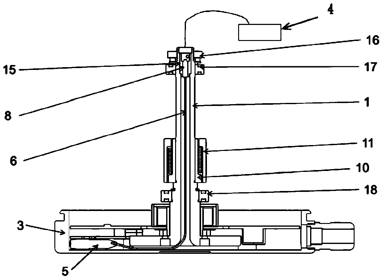
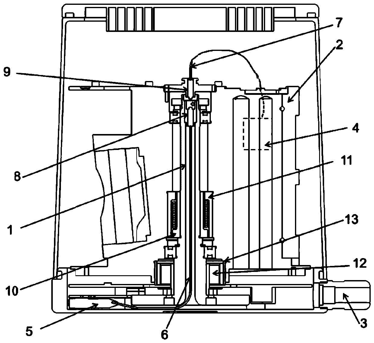
[0067] Embodiment 1. A laser radar, including a main shaft, a radar rotor and a communication component;
[0068] The main shaft is configured as a hollow structure;
[0069] The communication component includes a first communication module and a second communication module;
[0070] The first communication module is relatively fixed to the radar rotor;
[0071] The second communication module is fixedly arranged relative to the main shaft;
[0072] At least a part of the second communication module is disposed inside the main shaft.
Embodiment 2
[0073] Embodiment 2. The lidar according to embodiment 1, the second communication module includes a second optical fiber, and a part of the second optical fiber is disposed inside the main shaft.
Embodiment 3
[0074] Embodiment 3. According to the laser radar described in embodiment 1 or 2, the first communication module includes a first optical fiber, the first end of the first optical fiber is far away from the upper end of the main shaft, and the first end of the first optical fiber is The second end is adjacent to the upper end of the main shaft. And the end face of the second end of the first optical fiber is opposite to the end face of the first end of the second optical fiber at the upper end of the main shaft.
PUM
 Abstract
Description
Claims
Application Information