Piping for tank assemblies and tank assemblies for vehicles

A component and pipeline technology, which is applied in the field of plastic pipelines and vehicle tank components, can solve the problems of impossible to achieve reliable attachment of return pipelines, connection damage, etc.

CN109844299BActive Publication Date: 2021-10-15ROBERT BOSCH GMBH
6 Cites 0 Cited by

Patent Information

Authority / Receiving Office
CN · China
Patent Type
Patents(China)
Current Assignee / Owner
Publication Date
2021-10-15

Smart Images

  • Figure 1
    Figure 1
  • Figure 2
    Figure 2
  • Figure 3
    Figure 3
Patent Text Reader

Abstract

The invention relates to a pipeline of a tank assembly (1) comprising a conduit (20) having a joint area (21), wherein said joint area (21) comprises a fixing area (22) and a sealing area (23), wherein , the sealing area (23) is arranged closer to the free end (25) of the conduit (20) than the fixing area (22), wherein the sealing area (23) is configured to be able to A seal is achieved on the box component, and the fastening region (22) is provided for providing a releasable snap connection (6) to the box component.
Need to check novelty before this filing date? Find Prior Art

Description

technical field

[0001] The invention relates to a pipeline of a tank assembly, in particular a plastic pipeline, and a tank assembly of a vehicle. Background technique

[0002] Vehicles typically have a fuel tank for supplying fuel to the internal combustion engine. In some systems (in which the fuel pump is arranged in the tank) the pump known for example from DE 10 2014 209 292 A1 is arranged in the storage tank. The storage tank is filled with fuel so that sufficient fuel can be sucked in by the pump even when driving through fast curves. Furthermore, so-called saddle tanks are usually provided in tank assemblies, in which the first and second tank chambers are connected to each other via a connecting region. Here, the storage tank is only arranged in one of the tank chambers. In order to also empty the second tank chamber, a return line is provided which leads from the second tank chamber to the storage tank. Fastening of the fuel return line takes place here, which ...

Examples

Embodiment Construction

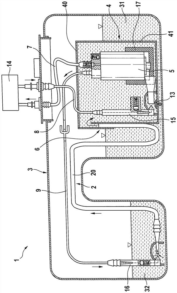
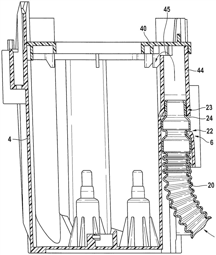
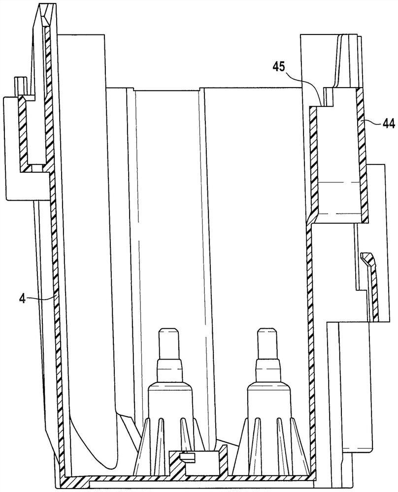
[0028] Refer below Figures 1 to 9 The box assembly 1 according to a preferred embodiment of the present invention is explained in detail.

[0029] The tank assembly 1 comprises a tank 3 in the form of a saddle tank having a first tank chamber 31 and a second tank chamber 32 which are interconnected. In the first tank chamber 31 is arranged a storage tank 4 in which a pump 5 is installed. The storage tank 4 comprises a tank-shaped base body 41 which is closed by means of a lid 40 .

[0030] The storage tank 4 is filled with fuel from the first tank chamber 31 via the filling valve 13 . A first line in the form of a delivery line 7 leads from the pump 5 in order to deliver fuel to the internal combustion engine 14 . Fuel not consumed in the internal combustion engine is led back into the storage tank 4 via the return line 8 . In this case, the return line 8 leads to a first suction jet pump 15 which conducts the fuel to the pump 5 via a filter 17 .

[0031] Arranged in the...