Charging circuit, terminal device, charging interface and charging device

A technology of charging circuit and charging interface, which is applied in the field of charging circuit, charging interface, charging equipment and terminal equipment, and can solve the problems of inconvenient operation of terminal equipment

Active Publication Date: 2019-06-14
VIVO MOBILE COMM CO LTD
View PDF6 Cites 2 Cited by
  • Summary
  • Abstract
  • Description
  • Claims
  • Application Information

AI Technical Summary

Problems solved by technology

[0006] The embodiment of the present invention provides a charging circuit, a terminal device, a charging interface and a charging device, so as to solve the problem of inconvenient operation of the terminal device existing in chargers in related technologies

Method used


Image

  • Charging circuit, terminal device, charging interface and charging device
  • Charging circuit, terminal device, charging interface and charging device
  • Charging circuit, terminal device, charging interface and charging device

Examples


Embodiment Construction

[0033] The following will clearly and completely describe the technical solutions in the embodiments of the present invention with reference to the accompanying drawings in the embodiments of the present invention. Obviously, the described embodiments are some of the embodiments of the present invention, but not all of them. Based on the embodiments of the present invention, all other embodiments obtained by persons of ordinary skill in the art without creative efforts fall within the protection scope of the present invention.

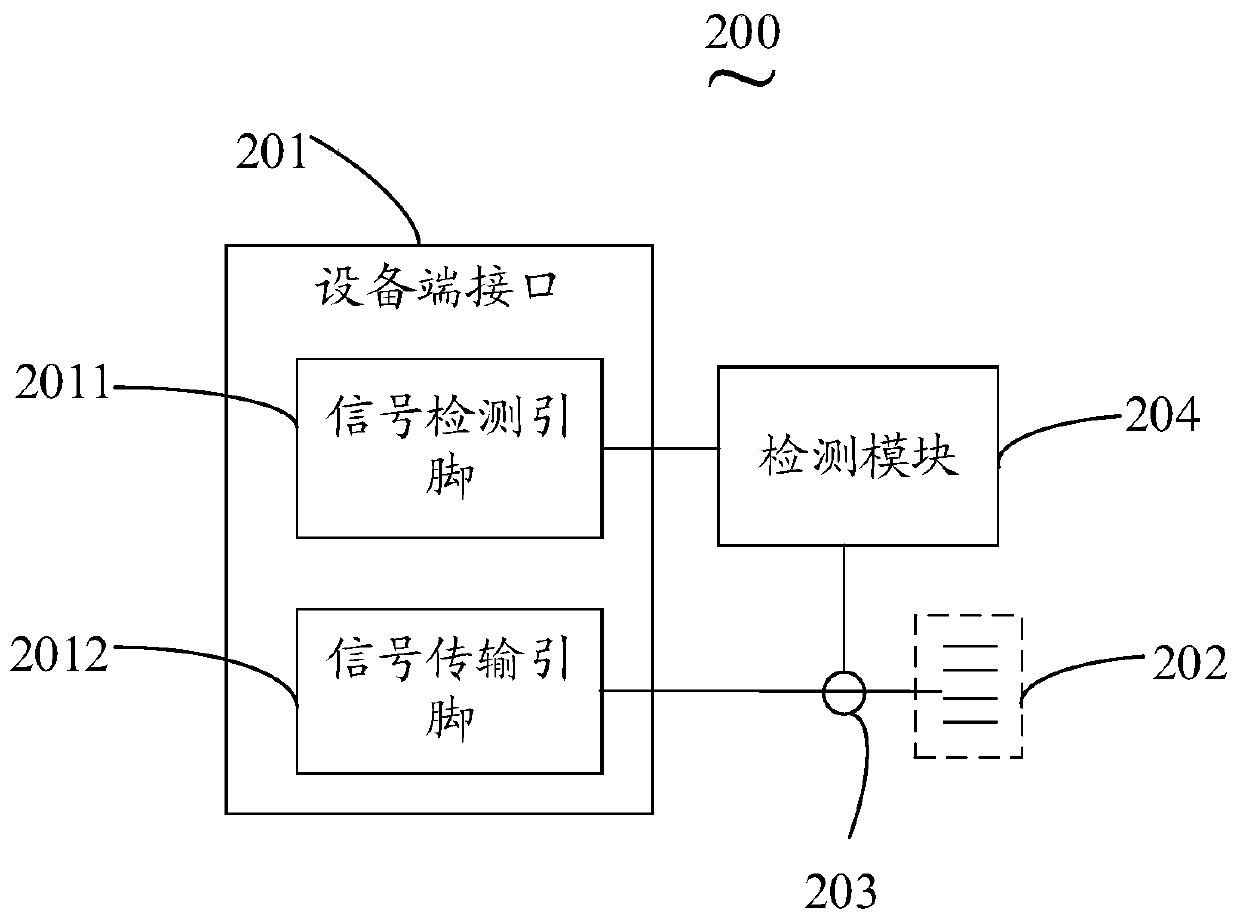
[0034] see figure 2 , is a circuit diagram of a charging circuit provided by an embodiment of the present invention. Such as figure 2 As shown, the charging circuit 200 includes: a device-side interface 201, N signal transmission connection lines 202, N switches 203 and a detection module 204, wherein the device-side interface 201 is provided with a signal detection pin 2011 and N signal detection pins 201 Transmission pins 2012, the N signal trans...


PUM


Abstract

The embodiment of the invention provides a charging circuit, a terminal device, a charging interface and a charging device, wherein the charging circuit comprises a device end interface, N signal transmission connecting lines, N switches and a detection module, a signal detection pin and N signal transmission pins are arranged on the device end interface, the N signal transmission pins are distributed in a normal N polygon, and N is an integer greater than or equal to 3: the first ends of the N switches are respectively connected with the N signal transmission pins; a detection end of the detection module is connected with a signal detection pin, a control end of the detection module is respectively connected with the control ends of the N switches for detecting a target voltage value of the signal detection pin and controlling the N switches according to the target voltage value, so that the N signal transmission pins are respectively connected with the N signal transmission connecting lines, and the target signal transmission connecting line is connected with the target signal transmission pin among the N signal transmission pins. By adoption of the charging circuit provided by the embodiment of the invention, the operation convenience of the terminal device can be improved.

Description

technical field [0001] The invention relates to the technical field of charging interfaces, in particular to a charging circuit, a terminal device, a charging interface and charging equipment. Background technique [0002] The technology of charging devices through chargers is becoming more and more widely used in computers, smart plus points and other devices. [0003] At present, in the process of connecting the charging interface and the terminal equipment interface, the direction of the charging interface and the terminal equipment interface must be matched to avoid damage to the equipment or disconnection caused by the reverse connection of the two. For example, the power supply of the charging terminal (Voltage Bus , VBUS) contacts are connected to the ground (Ground, GND) contacts of the terminal, which will cause a short circuit to the ground of the power supply, thus burning out the device. [0004] Such as figure 1 As shown, in the related art, after connecting t...

Claims


Application Information

Patent Timeline
Patent Type & Authority Applications(China)
IPC IPC(8): H02J7/00
Inventor 许贻勇
Owner VIVO MOBILE COMM CO LTD
Why Eureka
Try Eureka