An optical imaging system

An optical imaging system and image technology, applied in the direction of optical testing of flaws/defects, material analysis through optical means, scientific instruments, etc., to achieve accurate defect analysis, good imaging effect, and high image quality

Active Publication Date: 2020-11-06
江苏优普纳科技有限公司
View PDF5 Cites 0 Cited by
  • Summary
  • Abstract
  • Description
  • Claims
  • Application Information

AI Technical Summary

Problems solved by technology

[0005] To this end, the present invention provides an optical imaging system to solve or at least alleviate the above existing problems

Method used


Image

  • An optical imaging system
  • An optical imaging system
  • An optical imaging system

Examples


Embodiment Construction

[0029] Exemplary embodiments of the present disclosure will be described in more detail below with reference to the accompanying drawings. Although exemplary embodiments of the present disclosure are shown in the drawings, it should be understood that the present disclosure may be embodied in various forms and should not be limited by the embodiments set forth herein. Rather, these embodiments are provided for more thorough understanding of the present disclosure and to fully convey the scope of the present disclosure to those skilled in the art.

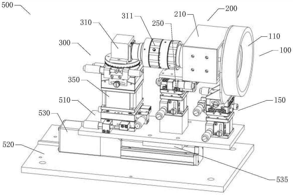
[0030] As mentioned above, the optical imaging system used to collect images of annular grooves in the prior art has more or less functional defects during use, so the present invention proposes an optical imaging system with more optimized performance 500. figure 1 A schematic structural diagram of the optical imaging system 500 of the present invention is shown.

[0031] It should be noted that the optical imaging system 500 of ...


PUM

PropertyMeasurementUnit
diameteraaaaaaaaaa
thicknessaaaaaaaaaa
lengthaaaaaaaaaa

Abstract

The invention discloses an optical imaging system which is suitable for acquiring an image of a groove at the end part of a tubular element. The optical imaging system comprises an annular light component, a coaxial light component and a shooting component, wherein the annular light component comprises an annular light source, and the annular light source is suitable for carrying out annular lightillumination on the groove; the coaxial light component comprises a coaxial light source, and the coaxial light source is arranged behind the annular light source, and is suitable for carrying out coaxial light illumination on the groove, wherein the optical axis of the coaxial light source is coaxial with the optical axis of the annular light source; and the shooting component comprises a cameraand a lens connected to the camera, and the shooting component is arranged behind the coaxial light source and is suitable for acquiring the image of the groove of the tubular element. The optical imaging system disclosed by the invention can accurately, clearly and comprehensively display the defects such as burrs, chipped edges and fractures on the slope, so that the accuracy of groove defect detection is improved.

Description

technical field [0001] The invention relates to the technical field of groove detection, in particular to an optical imaging system. Background technique [0002] As a clean, efficient, and pollution-free clean energy, nuclear energy has been widely used in military, production, and economic fields. Nuclear power generation has become an irresistible trend. Due to the characteristics of less residual waste, high energy utilization rate and high maturity of industrial application technology, heavy water reactors are widely used in nuclear power systems around the world. Nuclear fuel rods are the basic elements of heavy water reactors, and the quality of their processing and production is directly related to the normal operation of nuclear power plants. Because zirconium materials can still maintain good metal properties under high temperature and high radiation conditions, zirconium alloy tubes are generally used to wrap nuclear fuel to prevent fission products from overflo...

Claims


Application Information

Patent Timeline
Patent Type & Authority Patents(China)
IPC IPC(8): G01N21/88
CPCG01N21/8851G01N2021/8887
Inventor 刘坚姜潮索鑫宇董力成谢任兵杨世辉
Owner 江苏优普纳科技有限公司
Why Eureka
Try Eureka