Automatic braking control valve for tractor

An automatic brake and brake valve technology, applied in the field of tractors, can solve the problems of large space occupation, unrefined brake valve block, unfavorable heavy-duty tractors, etc., and achieve the effects of improving operating efficiency, enhancing comfort, and facilitating maintenance

Pending Publication Date: 2019-08-23
FIRST TRACTOR
View PDF2 Cites 1 Cited by
  • Summary
  • Abstract
  • Description
  • Claims
  • Application Information

AI Technical Summary

Problems solved by technology

For the above two cases, the first system mainly relies on the functions of electronic control, and the brake valve block is not refined. It uses three accumulators, which occupy a large space and cannot realize unilateral braking.
The second system cannot control the braking pressure of the brake valve well so as to completely simulate the pedal brake pedal to achieve flexible braking, which is especially unfav

Method used


Image

  • Automatic braking control valve for tractor
  • Automatic braking control valve for tractor
  • Automatic braking control valve for tractor

Examples


Embodiment Construction

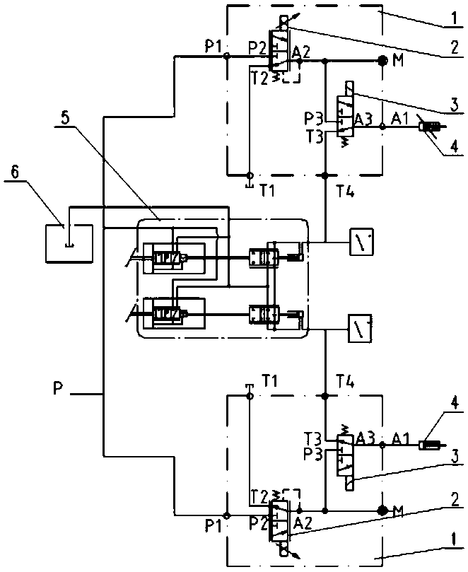
[0020] The present invention will be further described below in conjunction with the accompanying drawings and embodiments. figure 1 It is a schematic diagram of the brake system of an automatic brake control valve for a tractor of the present invention, figure 1 The brake 4, the brake booster 5, and the oil tank 6 do not belong to the content of the present invention, and are not described in detail here. figure 1 The upper and lower dotted boxes in the figure respectively represent the symmetrically installed left and right tractor brake valve blocks of the present application.

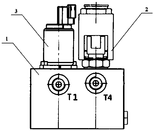
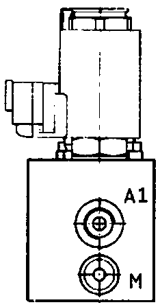
[0021] Such as Figure 2-7 As shown, an automatic brake control valve for a tractor mainly includes: a brake valve body 1 , a two-position three-way electric proportional pressure reducing valve 2 , and a two-position three-way electromagnetic reversing valve 3 . The two-position three-way electromagnetic reversing valve 3 and the two-position three-way electric proportional pressure reducing valv...


PUM


Abstract

An automatic braking control valve for a tractor comprises braking valve block valve bodies, two-position three-way electric proportional pressure reducing valves and two-position three-way solenoid directional control valves. The two-position three-way electric proportional pressure reducing valves and the two-position three-way solenoid directional control valves are sequentially mounted on thesame side surfaces of the corresponding braking valve block valve bodies; each of the braking valve block valve bodies is provided with five oil ports: a first oil inlet port, a first working oil port, a pressure measuring oil port, a first oil return port and a fourth oil return port; the first working oil ports of the braking valve block valve bodies are connected to brakes; the fourth oil return ports of the braking valve block valve bodies are connected to a braking booster; the first oil return ports of the braking valve block valve bodies are connected to a fuel tank; and the pressure measuring oil ports of the braking valve block valve bodies are closed with screw plugs. The control valve can realize any switching between manual braking and automatic braking of the tractor. The automatic braking is flexible braking and can completely simulate the situation of a manual brake pedal. Braking valve blocks on left and right sides are independent of each other, and can not only work independently to achieve single-side braking but also work simultaneously to achieve brake linkage.

Description

technical field [0001] The invention belongs to the field of tractors and relates to a control valve, in particular to an automatic braking control valve for tractors. Background technique [0002] At present, self-driving tractors have become the target of tractor companies at home and abroad, but the so-called self-driving tractors manufactured by some domestic tractor companies are only limited to automatic steering, electronically controlled lifting, etc. There is not much progress in automatic braking. The key technology is the lack of an automatic control valve that can switch freely. [0003] In the prior art, there are mainly two types of automatic braking of tractors: one is that the electronic control unit automatically collects signals when shifting gears and reversing, and after the signals are processed by the controller, the controller outputs signals to the automatic brake valve. The electromagnet opens the automatic brake valve to brake the wheels, prevents ...

Claims


Application Information

Patent Timeline
IPC IPC(8): B60T15/02
CPCB60T15/028
Inventor 段华威刘涛罗明泉雷蕾金鑫张举鑫王文卿裴高院赵鑫陈松
Owner FIRST TRACTOR
Why Eureka
Try Eureka