Test tube rack

A test tube rack and jack technology, which is used in test tube supports/clamps, local stirring dryers, and static material dryers, etc., can solve the problem of low test tube fixation stability, and achieve the effect of avoiding spillage.

Active Publication Date: 2019-08-30
SANMING UNIV
View PDF11 Cites 2 Cited by
  • Summary
  • Abstract
  • Description
  • Claims
  • Application Information

AI Technical Summary

Problems solved by technology

[0004] The purpose of the present invention is to provide a test tube rack to solve the technical problem that the test tube rack is not stable enough to fix the test tubes in the prior art

Method used


Image

  • Test tube rack
  • Test tube rack
  • Test tube rack

Examples


Embodiment Construction

[0029] In order to make the purpose, technical solution and advantages of the present invention clearer, the technical solution of the present invention will be described in detail below. Apparently, the described embodiments are only some of the embodiments of the present invention, but not all of them. Based on the embodiments of the present invention, all other implementations obtained by persons of ordinary skill in the art without making creative efforts fall within the protection scope of the present invention.

[0030] The following is attached with the manual Figure 1 to Figure 8 The technical solution of the present invention is described in detail.

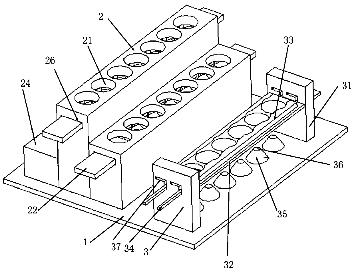
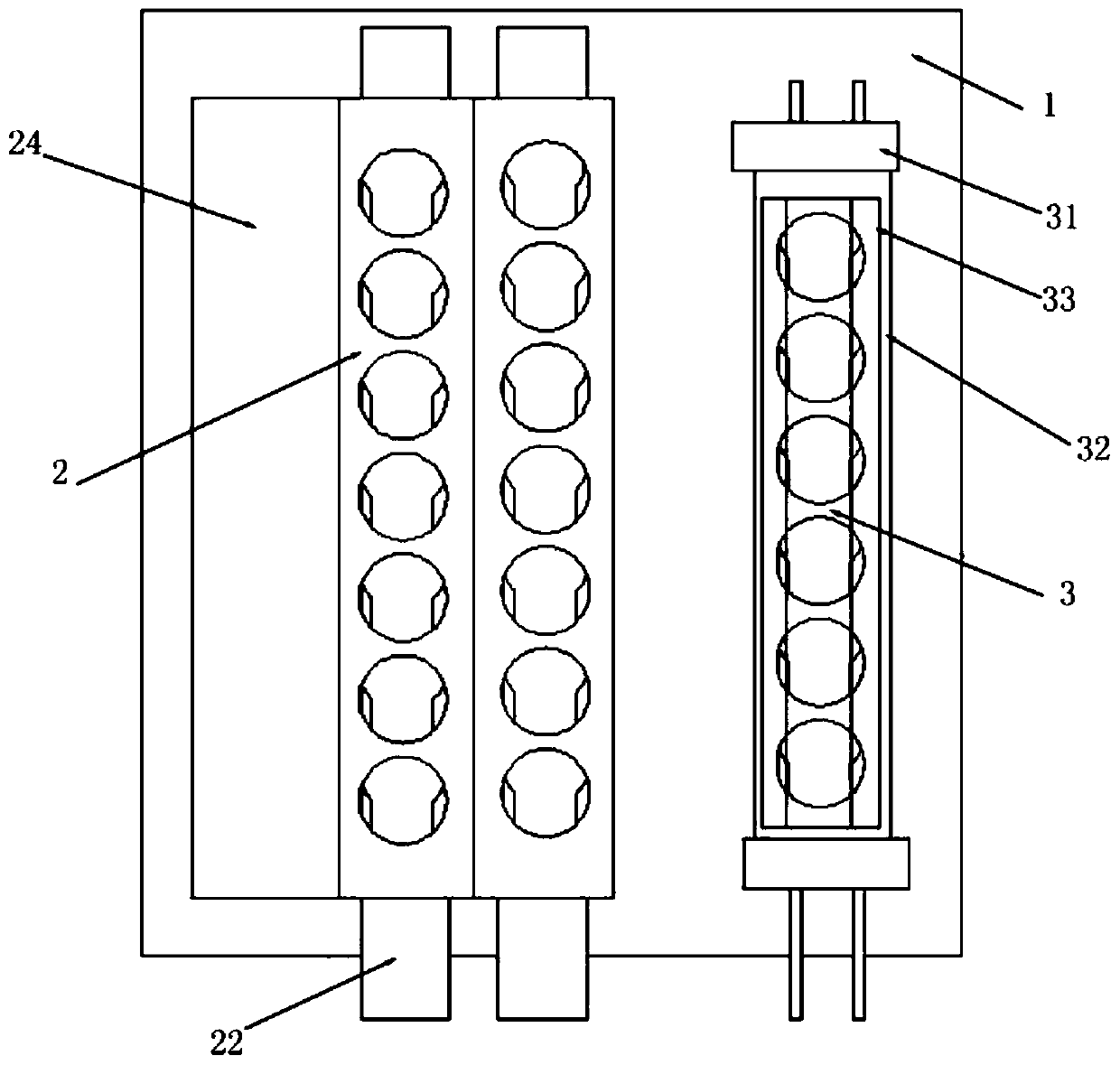
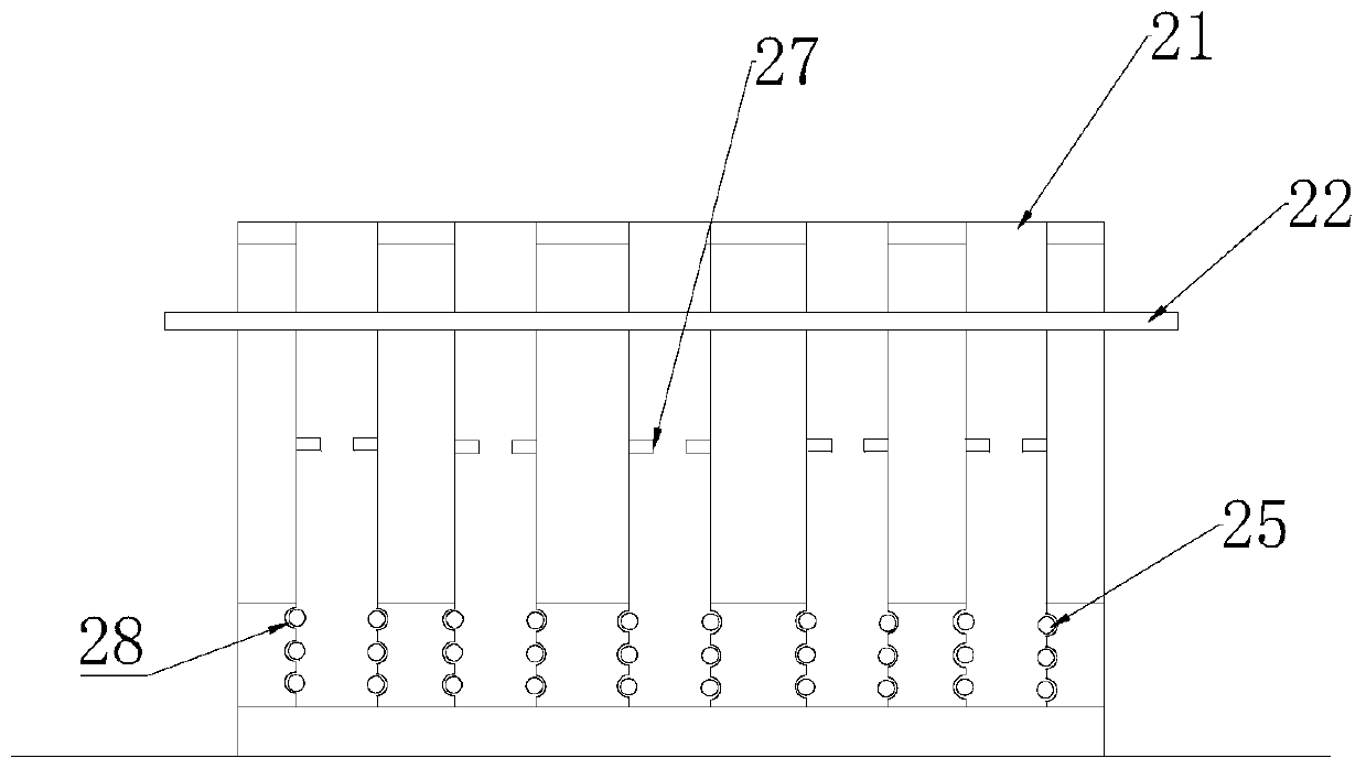
[0031] like figure 1 and Figure 4 as shown, figure 1 A schematic diagram of the three-dimensional structure of the test tube rack of the present invention is shown; Figure 4 It is a structural schematic diagram of the first splint in the test tube rack of the present invention. The present invention provides a t...


PUM


Abstract

The invention provides a test tube rack, relates to the technical field of test devices, and solves the technical problem of poor test tube fixing stability by a test tube rack in the prior art. The test tube rack comprises a base and at least one bracket arranged on the base, wherein multiple first insertion holes are formed in each bracket side by side, insertion slots enabling two ends of the bracket to be through are formed in the transverse direction of the bracket, first clamping plates are arranged in the insertion slots in a sliding manner, and multiple first clamp holes which correspond to the first insertion holes and can limit test tubes located in the first insertion holes are formed in the first clamp plates. When the test tube rack is used for placing test tubes, the test tubes can be prevented from shaking in a moving process, overflowing of a liquid in the test tubes is avoided, and stability of the test tubes is guaranteed.

Description

technical field [0001] The invention relates to the technical field of experimental equipment, in particular to a test tube rack. Background technique [0002] The test tube rack is a kind of chemical experimental instrument, and it is the most basic experimental instrument used in chemical laboratories to place and dry test tubes. Test tube racks in the prior art are usually wooden or bamboo racks, usually with 6 holes and 12 holes. [0003] The applicant finds that the prior art at least has the following technical problems: the test tube rack in the prior art is provided with round holes and small wooden posts for inserting test tubes, and for the convenience of taking and placing the test tubes, the inner diameter of the insertion hole of the test tube rack is often larger than that of the test tube. The outer diameter of the test tube rack is larger, that is, there is a gap between the inner diameter of the test tube rack and the test tube, so in the process of moving ...

Claims


Application Information

Patent Timeline
Patent Type & Authority Applications(China)
IPC IPC(8): B01L9/06F26B9/10F26B21/00
CPCB01L9/06F26B9/10F26B21/00
Inventor 邢建宏王春宝唐秀梅陈锦芳
Owner SANMING UNIV
Why Eureka
Try Eureka