
Fireproof protection type transformer fence device for transformer
A guardrail device and transformer technology, applied in fire rescue and other directions, can solve the problems of flame extinguishing, etc., and achieve the effects of reducing hazards, convenient operation, and low production cost
- Summary
- Abstract
- Description
- Claims
- Application Information
AI Technical Summary
Problems solved by technology
Method used
Image

Examples
Embodiment Construction
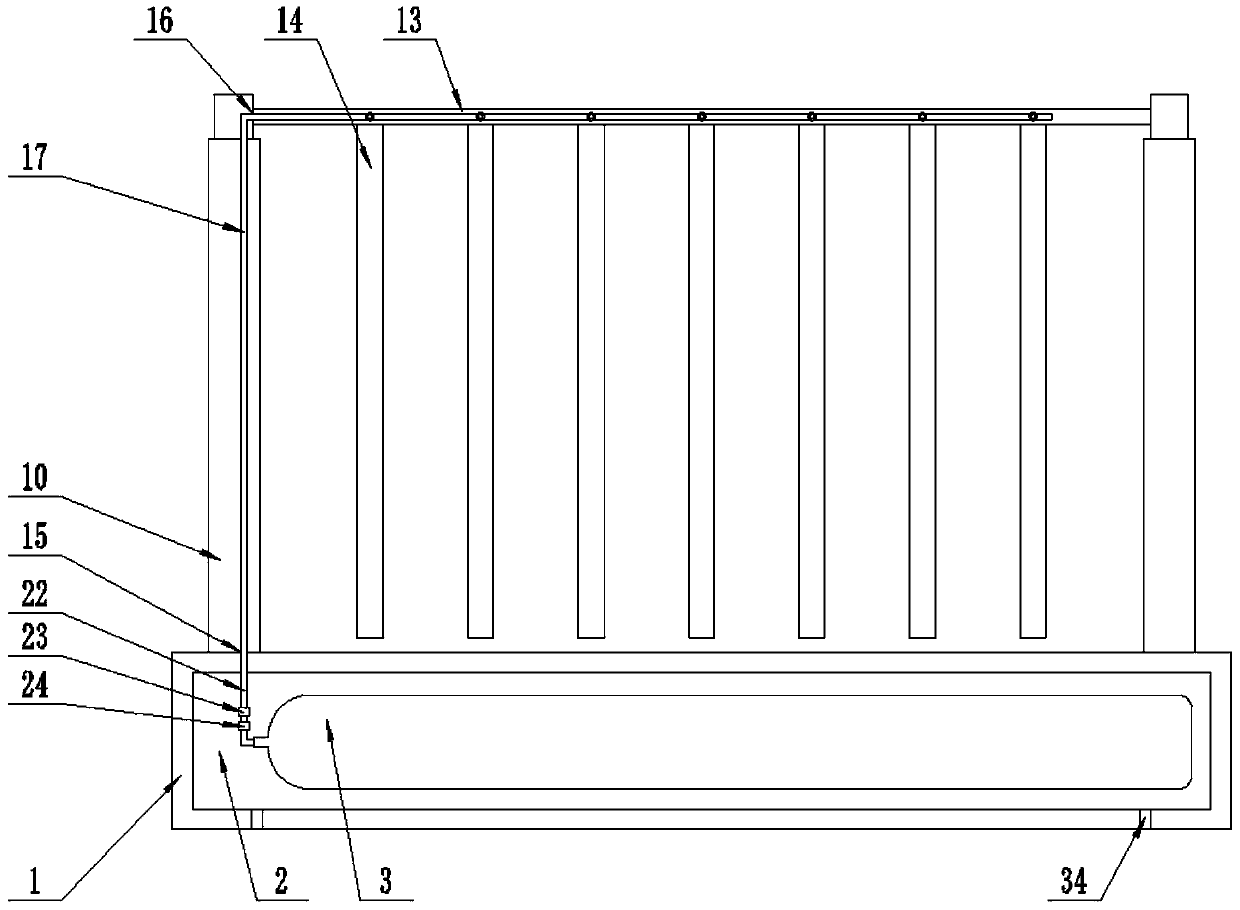
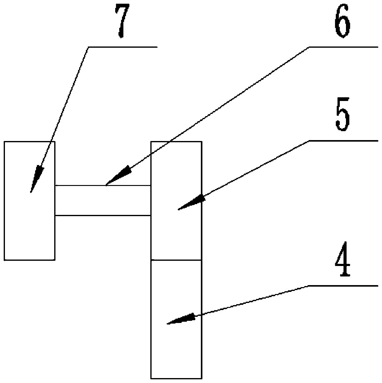
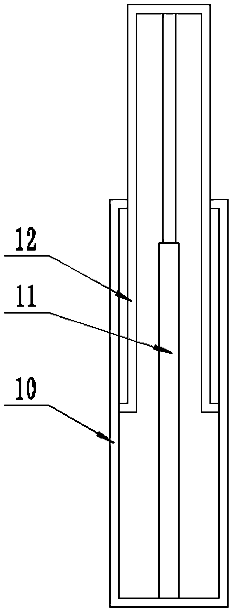
[0022] The present invention is specifically described below in conjunction with accompanying drawing, as Figure 1-6 As shown, a transformer guardrail device for fire protection on a transformer includes a base 1, the base 1 is fixedly installed on the ground, and a carbon dioxide storage device is provided inside the base 1, and the carbon dioxide storage device is opened A groove 2 on the side surface of the base 1, a carbon dioxide storage tank 3 located in the groove 2 and movably connected to the groove 2, two bearing seats 4 fixedly connected to the groove 2 on both sides of one end of the lower surface of the groove 2, The fixed bearing 5 located on the bearing seat 4 and fixedly connected with the bearing seat 4, the rotating shaft 6 located in the fixed bearing 5 and fixedly connected with the fixed bearing 5, the rotating bearing 7 located at one end of the rotating shaft 6 and fixedly connected with the rotating shaft 6, and the rotating shaft located in the rotatin...
PUM
 Abstract
Description
Claims
Application Information