
Production frame device for automobile clutch bearing
A clutch and frame device technology, which is applied in positioning devices, feeding devices, supports, etc., can solve the problems that the bearings cannot be stably fixed, and the bearings with different diameters cannot be processed, etc., and achieve the effect of simple structure and convenient use
- Summary
- Abstract
- Description
- Claims
- Application Information
AI Technical Summary
Problems solved by technology
Method used
Image

Examples
Embodiment 1
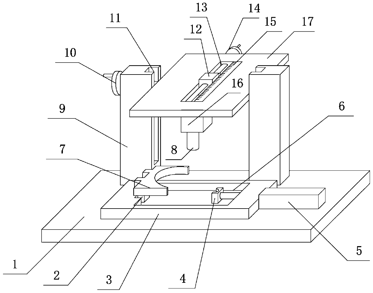
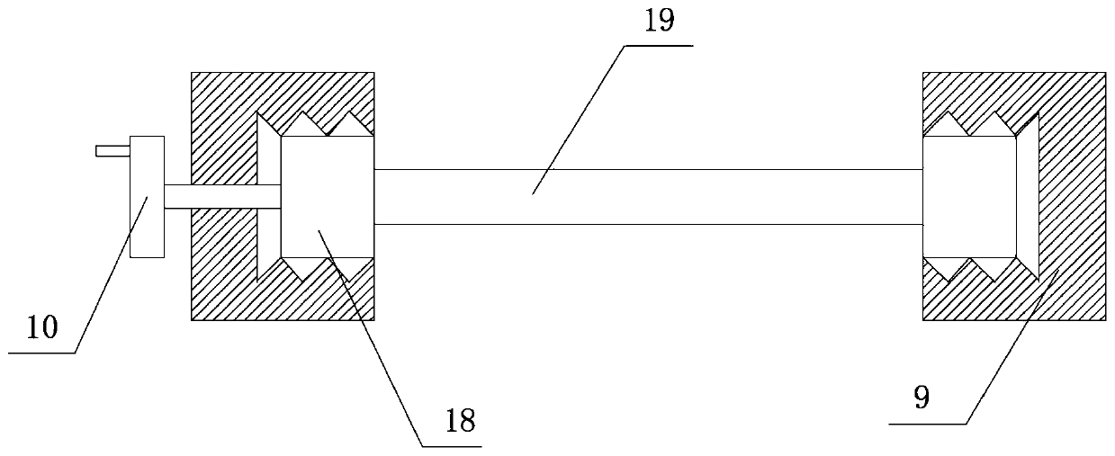
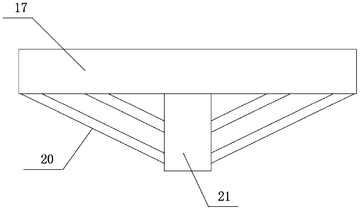
[0020] see Figure 1-3 As shown, a production frame device for automobile clutch bearings includes a base 1, a fixed frame 3 is arranged on the top of the base 1, a groove 6 is arranged inside the fixed frame 3, a groove 2 is arranged on the side wall of the groove 6, and the inside of the groove 2 is Fixed block 7 is installed, and electric telescopic rod 5 is installed on the side wall of fixed frame 3, and one end of electric telescopic rod 5 is connected with movable block 4, and support column 9 is set on one side of fixed frame 3, and the first runner 10 is installed on the side wall of support column 9, and the support column 9. A chute 11 is arranged inside the chute 11, and a roller 18 is installed inside the chute 11. One side of the roller 18 is connected to a rotating shaft 19, and the side wall of the rotating shaft 19 is provided with a support plate 17, that is, by rotating the first runner 10, the roller 18 can move downward, and then Make the roller 18 drive t...
Embodiment 2
[0022] read on Figure 1-3 , the difference with Embodiment 1 is that: the inside of the fixed block 7 and the movable block 4 are provided with arc-shaped grooves, and the movable block 4 and the electric telescopic rod 5 are connected by threads, so that the fixed block 7 and the movable block 4 Capable of fixing automobile clutch bearings. The inner side wall of the chute 11 and the outer side wall of the roller 18 are provided with hobbing gears, and the roller 18 is fixedly connected to the rotating shaft 19, and the rotating shaft 19 runs through the support plate 17, which is convenient for the user to control the connection between the cutter head 8 and the clutch bearing. distance between. The slider 12 is threadedly connected to the bolt rod 13 , and the bolt rod 13 is movably connected to the support plate 17 , so that the user can control the moving distance of the slider 12 by turning the second rotating wheel 15 . There is a fixed connection between the motor 1...
PUM
 Abstract
Description
Claims
Application Information