Headphone charging box

A technology for charging boxes and earphones, which is applied in the direction of handset/headphone accessories, rechargeable batteries/devices, etc. It can solve the problems of affecting the service life of charging boxes, damage to the joint position of the rotating shaft, and single flipping method, achieving high reliability and long service life. Long, easy-to-operate effect

Active Publication Date: 2021-02-19
GEER TECH CO LTD
View PDF8 Cites 0 Cited by
  • Summary
  • Abstract
  • Description
  • Claims
  • Application Information

AI Technical Summary

Problems solved by technology

[0003] At present, the flipping method of the earphone charging box on the market is relatively simple, and most of them are manually flipping up and down. Specifically, one side of the upper shell of the charging box is connected to the lower shell through a rotating shaft, and the other side is connected by magnetic attraction or buckle. On the corresponding side of the lower case, when the cover is opened to expose the earphones, the user needs to apply force to move the upper case to separate the magnetic attraction or buckle structure of the upper case and the lower case. This kind of flip-opening and closing structure requires the user to apply force on the On the upper case, if the user uses too much force, it is likely to cause damage to the joint position of the shaft and affect the service life of the charging box

Method used


Image

  • Headphone charging box
  • Headphone charging box
  • Headphone charging box

Examples


Embodiment 1

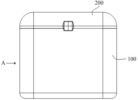
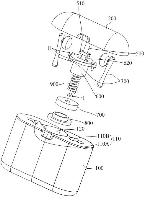
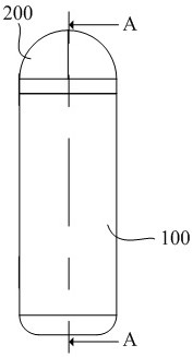
[0039] This embodiment is an earphone charging box, refer to Figure 1 to Figure 4 , including an upper case 200 and a lower case 100, the lower case 100 is formed with an earphone accommodation chamber 110 for accommodating the earphone 300, when the earphone 300 needs to be charged or stored, it is placed in the earphone accommodation chamber 110 so that it can be charged by the earphone charging box For storage or charging; the upper case 200 is used to open or close the lower case 100 . In this embodiment, the upper case 200 can move up and down relative to the lower case 100 under external force, and when it moves downward relative to the lower case 100 until it is matched with the lower case 100, the lower case 100 will be closed. Open the lower case 100 when the side away from the lower case 100 rises to separate from the lower case 100, and when the upper case 200 rises enough for the user to take out the earphone 300, the user can easily take out the earphone 300; F...

Embodiment 2

[0051] Different from Embodiment 1, the stop structure in this embodiment includes a first protrusion 630 formed on the inner wall of the through hole 610 of the first stop block 600 and a second protrusion 520 formed on the outer wall of the guide shaft 500 , At least one of the first protrusion 630 and the second protrusion 520 is an elastic protrusion. Then when the guide shaft 500 rises, the extrusion deformation of the second protrusion 520 and the first protrusion 630 on the inner wall of the through hole 610 makes the second protrusion 520 upwardly cross the first protrusion 630 to stop at the first protrusion 630. The positioning of the guide shaft 500 is realized on the protrusion 630, thereby keeping the upper case 200 in the state of opening the lower case.


PUM


Abstract

The invention provides an earphone charging box, which realizes the lifting and closing of the upper case. Compared with the existing flip-type opening and closing cover, the force of lifting and closing the cover is easy to control, and has high reliability and long service life. The earphone charging box includes a lower case and an upper case, and the upper case can move up and down relative to the lower case under external force; it also includes: a guide hole and a guide shaft, the guide hole is formed in the lower case and extends vertically, and the guide shaft is located at The upper shell is below and extends vertically, its top end is fixedly connected to the upper shell, and its bottom end is inserted into the guide hole, and can be driven by the upper shell to move up and down along the guide hole. The earphone charging box of the present invention can lift and lower the upper case to open or close the lower case, and has simple and convenient operation, high reliability and long service life.

Description

technical field [0001] The invention relates to the structural improvement of an earphone charging box. Background technique [0002] Most earphones are usually equipped with charging boxes, such as wireless earphones, TWS earphones, etc. Taking TWS earphones as an example, the charging box of TWS earphones is a necessary accessory when purchasing earphones, providing storage and charging functions for TWS earphones. [0003] At present, the flipping method of the earphone charging box on the market is relatively simple, and most of them are manually flipping up and down. Specifically, one side of the upper shell of the charging box is connected to the lower shell through a rotating shaft, and the other side is connected by magnetic attraction or buckle. On the corresponding side of the lower case, when the cover is opened to expose the earphones, the user needs to apply force to move the upper case to separate the magnetic attraction or buckle structure of the upper case an...

Claims


Application Information

Patent Timeline
Patent Type & Authority Patents(China)
IPC IPC(8): H04R1/10
CPCH04R1/1025
Inventor 张传涛
Owner GEER TECH CO LTD
Why Eureka
Try Eureka