Excavator base

An excavator and base technology, applied in the field of mechanical processing equipment, can solve the problems of inactivity, shrinking construction machinery market sales, and inability to adjust the height, and achieve the effect of overcoming the inability to adjust the height of the base

Inactive Publication Date: 2020-03-03
谭秀珍
View PDF0 Cites 0 Cited by
  • Summary
  • Abstract
  • Description
  • Claims
  • Application Information

AI Technical Summary

Problems solved by technology

In fact, there are both risk factors and income considerations, because bank credit is not active in promoting the construction of affordable housing, which indirectly led to the shrinking sales of construction machinery market in the second quarter of 2011
[0003] However, the bases of existing excavators are all fixed installations. When encountering some special working conditions, the height cannot be adjusted in a targeted manner.

Method used


Image

  • Excavator base

Examples


Embodiment 1

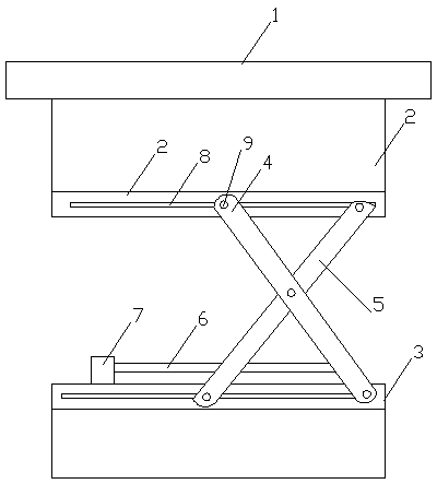
[0017] An excavator base, characterized in that it includes a base body 1, a mounting frame 2 is provided at the bottom of the base body 1, a lifting device is installed under the mounting frame 2, and a lifting device is installed at the bottom of the lifting device. Fixed frame 3, described lifting device comprises the first lifting rod 4 and the second lifting rod 5 that are arranged crosswise, the middle part of described first lifting rod 4 and the second lifting rod 5 are mutually hinged, and described first lifting rod 4 The bottom of the second lifting rod 5 is connected with the first connecting rod 6, and the outside of the second lifting rod 5 is connected with a cylinder 7, and the cylinder 7 is connected with the second lifting rod 5 through a connecting rod. The base body 1 of the present application can achieve the effect of raising and lowering according to actual needs, and overcomes the problem that the height of the base cannot be adjusted in the prior art. ...

Embodiment 2

[0019] An excavator base, characterized in that it includes a base body 1, a mounting frame 2 is provided at the bottom of the base body 1, a lifting device is installed under the mounting frame 2, and a lifting device is installed at the bottom of the lifting device. Fixed frame 3, described lifting device comprises the first lifting rod 4 and the second lifting rod 5 that are arranged crosswise, the middle part of described first lifting rod 4 and the second lifting rod 5 are mutually hinged, and described first lifting rod 4 The bottom of the second lifting rod 5 is connected with the first connecting rod 6, and the outside of the second lifting rod 5 is connected with a cylinder 7, and the cylinder 7 is connected with the second lifting rod 5 through a connecting rod.

[0020] There are two groups of lifting devices, and the two groups of lifting devices are symmetrically distributed.

[0021] The cylinder 7 is fixed on the fixed frame 3 .

[0022] The bottom of the insta...


PUM


Abstract

The invention belongs to the field of machining equipment, in particular to an excavator base. The excavator base comprises a base body, wherein a mounting frame is arranged at the bottom of the basebody, a lifting device is mounted the lower portion of the mounting frame, a fixing frame is mounted at the bottom of the lifting device, the lifting device comprises a first lifting rod and a secondlifting rod which are arranged in a crossed mode, the middle part of the first lifting rod is hinged to the middle part of the second lifting rod, the bottom of the first lifting rod is connected withthe bottom of the second lifting rod through a first connecting rod, an air cylinder is connected to the outer part of the second lifting rod, and the air cylinder is connected with the second lifting rod through a connecting rod. According to the base body of the excavator base, the effect of raising and lowering can be achieved according to actual requirements, the problem that the height of abase is not adjustable in the prior art is solved, and the second lifting rod is driven by the air cylinder to horizontally move through driving of the first lifting rod and the second lifting rod inthe lifting device, so that the bottom of the second lifting rod does horizontal reciprocating motion, and the height of the mounting frame is increased and lowered.

Description

technical field [0001] The application belongs to the field of mechanical processing equipment, in particular to an excavator base. Background technique [0002] my country began to develop and develop excavator products in the late 1960s. After more than 40 years, especially in the past 30 years of reform and opening up, China's excavator manufacturing industry has developed particularly rapidly. According to data from the National Bureau of Statistics, in 2010, there were 252 enterprises above designated size in China's excavator manufacturing industry, with sales of 169.785 billion yuan and product sales profits of 25.367 billion yuan. The total profit was 21.406 billion yuan, a year-on-year increase of more than 80%. China's excavator market is increasing at an average rate of 30%, becoming one of the largest markets in the world. From the perspective of development, China is in the peak period of infrastructure construction in road transportation, energy and water cons...

Claims


Application Information

Patent Timeline
Patent Type & Authority Applications(China)
IPC IPC(8): E02F9/00
CPCE02F9/00
Inventor 谭秀珍
Owner 谭秀珍
Why Eureka
Try Eureka