Damping ball mill convenient to move

A shock-absorbing ball and mill technology, applied in non-rotating vibration suppression, grain processing, etc., can solve problems such as inconvenient movement and large vibration, and achieve the effects of improving crushing efficiency, reducing vibration, and solving large vibration

Pending Publication Date: 2020-03-17
ZHUZHOU LIANXIN METAL CO LTD
View PDF12 Cites 9 Cited by
  • Summary
  • Abstract
  • Description
  • Claims
  • Application Information

AI Technical Summary

Problems solved by technology

[0003] The existing ball mill vibrates greatly during work, and it is inconvenient to move, so it is difficult to meet people's needs

Method used


Image

  • Damping ball mill convenient to move
  • Damping ball mill convenient to move
  • Damping ball mill convenient to move

Examples


Embodiment 1

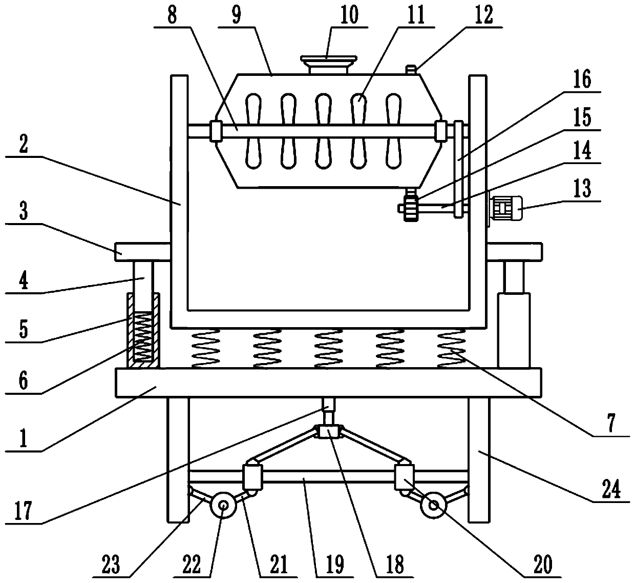
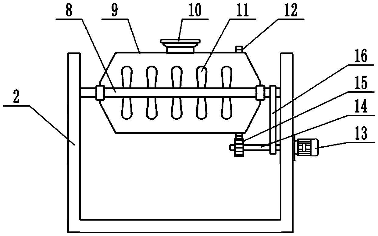
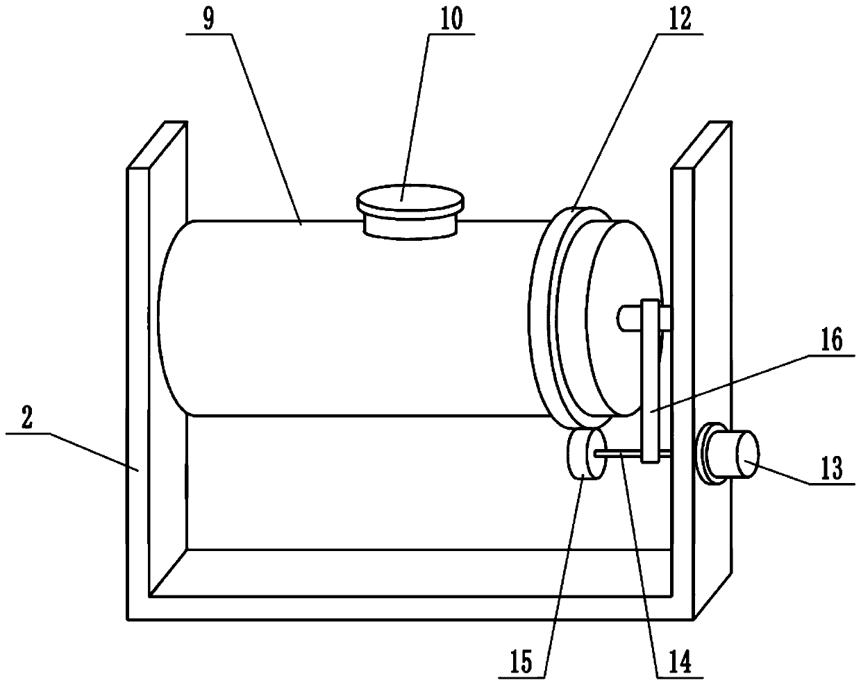
[0021] see Figure 1-3 , in an embodiment of the present invention, a shock-absorbing ball mill that is easy to move includes a table top 1, a mounting frame 2, a stirring shaft 8 and a cylinder body 9, a mounting frame 2 is provided above the table top 1, and the left and right sides of the mounting frame 2 are respectively The fixed block 3 is fixedly connected, the lower surface of the fixed block 3 is fixedly connected with the guide rod 4, the lower end of the guide rod 4 is provided with a sleeve 5, the guide rod 4 is slidably connected with the sleeve 5, and the guide rod 4 can be mounted on the sleeve 5. Sliding up and down inside the sleeve 5, a buffer spring 6 is installed inside the sleeve 5, and the buffer spring 6 can play a certain buffering effect. The upper surface is fixedly connected, and the shock-absorbing spring 7 is used for shock absorption to reduce the vibration generated during the operation of the device. The inside of the mounting frame 2 is equippe...

Embodiment 2

[0023] On the basis of Embodiment 1, a support plate 24 is installed at the bottom of the table top 1, and there are two support plates 24, which are symmetrically arranged left and right. The lower surface of the table top 1 is fixedly connected with a telescopic mechanism 17, and the telescopic mechanism 17 is an electro-hydraulic telescopic cylinder. The extending end of telescoping mechanism 17 is fixedly connected with lifting block 18, controls telescoping mechanism 17 telescopically, can drive lifting block 18 to move up and down, the below of lifting block 18 is provided with guide rod 19, and the left and right ends of guide rod 19 are connected with support plate respectively. 24 is fixedly connected, the guide rod 19 is covered with a slide block 20, the slide block 20 is slidably connected with the guide rod 19, the slide block 20 can slide left and right along the guide rod 19, there are two slide blocks 20, symmetrically arranged left and right, the slide block Th...

Embodiment 1、 Embodiment 2

[0024] Combined with Embodiment 1 and Embodiment 2, the working principle of the present invention is: put the material to be crushed into the barrel 9 through the feeding port 10, start the motor 13, and drive the driving shaft 14 to rotate, thereby driving the ring gear 12 to rotate through the gear 15 , so as to drive the cylinder body 9 to rotate, and at the same time, when the drive shaft 14 rotates, the agitating shaft 8 is driven to rotate through the transmission belt 16, thereby driving the agitating blade 11 to rotate, and the agitating blade 11 is used to agitate the material to be crushed to improve the crushing efficiency. The inside of the sleeve 5 A buffer spring 6 is installed, and the buffer spring 6 can be used for a certain buffering effect, and the shock-absorbing spring 7 can be used for shock absorption to reduce the vibration generated when the device is in operation. When the device needs to be moved, the telescopic mechanism 17 is controlled. Elongation...


PUM


Abstract

The invention relates to the field of grinding equipment. More particularly, the present invention relates to the damping ball mill which is convenient to move. The ball mill comprises a tabletop, a mounting frame, a stirring shaft and a barrel body; a mounting frame is arranged above the tabletop; damping springs are distributed on the lower surface of the mounting frame; the lower ends of the damping springs are fixedly connected with the upper surface of the tabletop; the stirring shaft is mounted in the mounting frame; the middle part of the stirring shaft is sleeved with the barrel body;the barrel body is rotationally connected with the stirring shaft; stirring blades are distributed on the stirring shaft; a gear ring is sleeved on the barrel body; the outer side wall of the mountingframe is fixedly connected with a motor; the shaft extension end of the motor is fixedly connected with a driving shaft; the driving shaft is sleeved with a gear; and the gear is meshed with the gearring. According to the invention, the motor is used for driving the barrel body to rotate, and the stirring blades are used for stirring to-be-crushed materials, so the crushing efficiency is improved; and the damping springs can achieve a certain damping effect. The damping springs can achieve the damping effect, so the vibration generated during operation of the ball mill is reduced, and the ball mill can be conveniently pushed to move by arranging the rolling shaft capable of ascending and descending.

Description

technical field [0001] The invention relates to the field of grinding equipment, more specifically, a shock-absorbing ball mill that is easy to move. Background technique [0002] The ball mill is the key equipment for crushing the material after it is crushed. This type of grinding machine is filled with a certain number of steel balls in its cylinder as the grinding medium. It is widely used in cement, silicate products, new building materials, refractory materials, chemical fertilizers, black and non-ferrous metal beneficiation, glass ceramics and other production industries, for dry or wet grinding of various ores and other grindable materials. Ball mills are suitable for grinding various ores and other materials, and are widely used in mineral processing, building materials and chemical industries. They can be divided into dry and wet grinding methods. According to different ore discharge methods, it can be divided into grid type and overflow type. [0003] The exist...

Claims


Application Information

Patent Timeline
Patent Type & Authority Applications(China)
IPC IPC(8): B02C17/16B02C17/18B02C17/24B02C23/04F16F15/04
CPCB02C17/16B02C17/163B02C17/18B02C17/1825B02C17/24B02C23/04F16F15/04
Inventor 李浒李伯如李伯胜李长
Owner ZHUZHOU LIANXIN METAL CO LTD
Why Eureka
Try Eureka