Pump body assembly and sliding vane compressor with same

A component and pump body technology, applied in the field of compressors, can solve problems such as loud noise and affect user experience, and achieve the effect of reducing noise

Pending Publication Date: 2020-04-17
GREE ELECTRIC APPLIANCES INC
View PDF0 Cites 7 Cited by
  • Summary
  • Abstract
  • Description
  • Claims
  • Application Information

AI Technical Summary

Problems solved by technology

[0004] The main purpose of the present invention is to provide a pump body assembly and a vane compressor with it, so as to solve the problem in the prior art that the vane compressor produces relatively loud noise during operation and affects the user experience

Method used


Image

  • Pump body assembly and sliding vane compressor with same
  • Pump body assembly and sliding vane compressor with same
  • Pump body assembly and sliding vane compressor with same

Examples


Embodiment 1

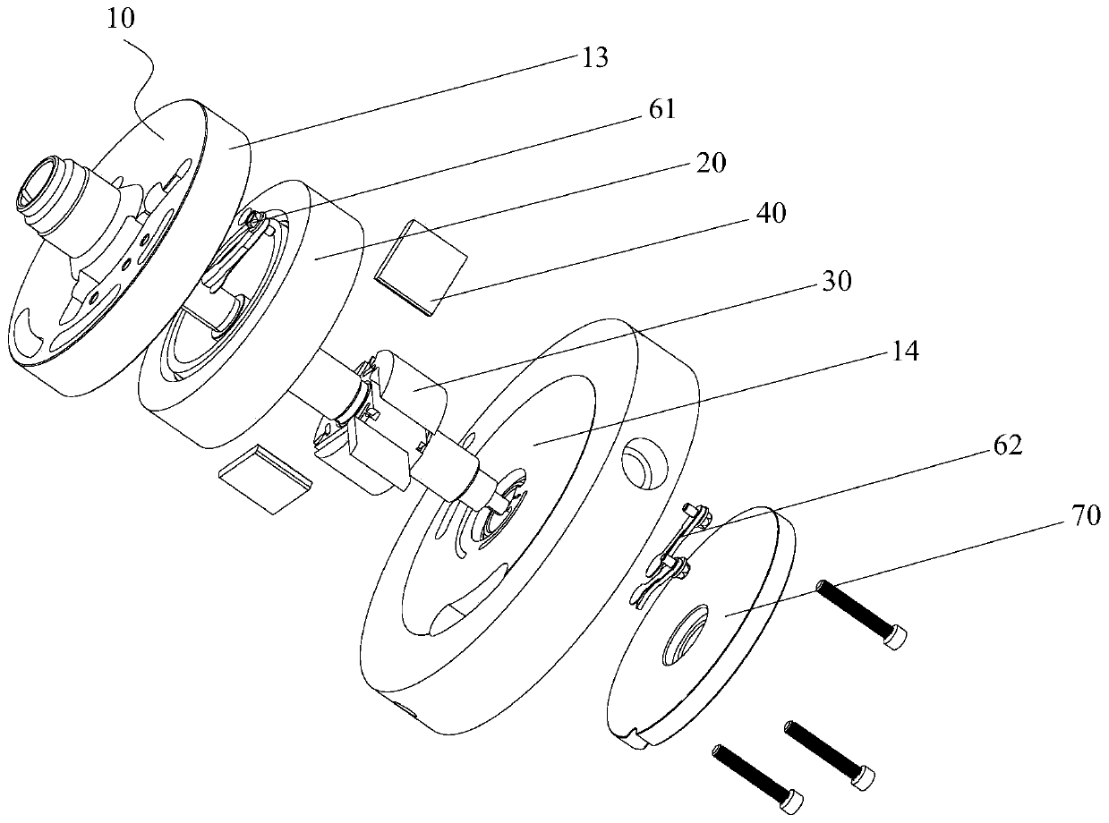
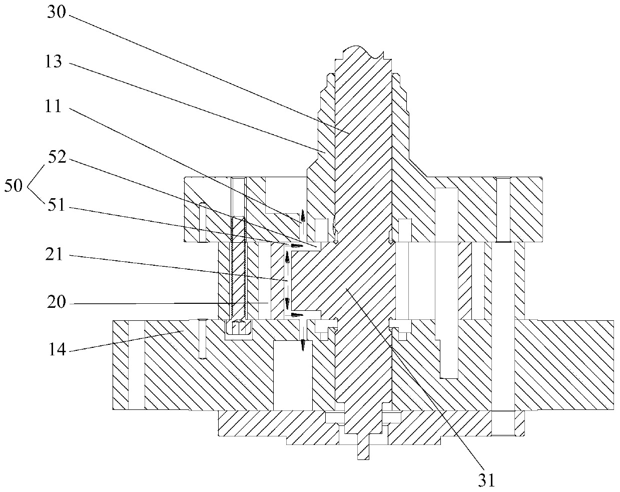
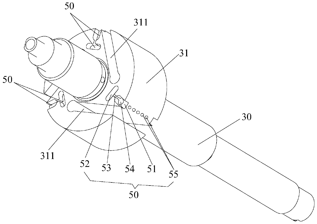
[0037] like figure 1 and figure 2 As shown, the pump body assembly includes a flange 10, a cylinder 20, a rotating shaft 30 and a plurality of sliding vanes 40, the sliding vanes 40 are slidably arranged on the rotor portion 31 of the rotating shaft 30, and the rotor portion 31 is located in the cylinder 20, the pump body assembly An exhaust assembly 50 is also included, and the exhaust assembly 50 is arranged on the rotor part 31 . The exhaust assembly 50 includes a first exhaust structure 51 , a noise reduction structure 52 and a connecting channel 53 . The first exhaust structure 51 extends to the outer peripheral surface of the rotor part 31 . An anechoic chamber is formed between the anechoic structure 52 and the flange 10 . The connection channel 53 communicates with the first exhaust structure 51 , the muffler chamber communicates with the first exhaust structure 51 through the connection channel 53 , and the flange 10 includes an exhaust hole 11 . Wherein, the anec...

Embodiment 2

[0069] The difference between the pump body assembly in the second embodiment and the first embodiment is that the shape of the air inlet hole 55 is different.

[0070] like Figure 8 As shown, the air inlet 55 is a hexagonal structure. The above arrangement makes the processing of the air intake hole 55 easier and simpler, and reduces the processing cost and difficulty of the rotor portion 31 .

Embodiment 3

[0072] The difference between the pump body assembly in the third embodiment and the first embodiment is that the shape of the air inlet hole 55 is different.

[0073] like Figure 9 As shown, the air intake hole 55 is a triangular structure. The above arrangement makes the processing of the air intake hole 55 easier and simpler, and reduces the processing cost and difficulty of the rotor portion 31 .

[0074] From the above description, it can be seen that the above-mentioned embodiments of the present invention have achieved the following technical effects:

[0075] The anechoic structure has an anechoic cavity, or an anechoic cavity is formed between the anechoic structure and the flange. The connecting channel communicates with the first exhaust structure, the anechoic cavity communicates with the first exhaust structure through the connecting channel, and the anechoic cavity and the connecting channel form a Helmholtz resonance body. During the operation of the pump bo...


PUM


Abstract

The invention provides a pump body assembly and a sliding vane compressor with the same, wherein the pump body assembly comprises a flange, a cylinder, a rotary shaft and a plurality of sliding vanes.The sliding vanes are slidably arranged on a rotor part of the rotary shaft. The rotor part is located in the cylinder. The pump body assembly further comprises an exhaust assembly. The exhaust assembly is arranged on the rotor part and comprises a first exhaust structure, a noise elimination structure and a connection channel. The first exhaust structure extends to the peripheral face of the rotor part. The noise elimination structure is provided with a noise elimination cavity, or a noise elimination cavity is formed between the noise elimination structure and the flange. The connection channel communicates with the first exhaust structure. The noise elimination cavity communicates with the first exhaust structure through the connection channel. The flange comprises an exhaust hole. Thenoise elimination cavity and the connection channel form a Helmholtz resonator which absorbs aerodynamic noise in air passing through the Helmholtz resonator. According to the pump body assembly andthe sliding vane compressor with the same, the problems that in the prior art, a sliding vane compressor generates large noise in the operation process, and use experience of a user is influenced aresolved effectively.

Description

technical field [0001] The invention relates to the technical field of compressors, in particular to a pump body assembly and a sliding vane compressor having the same. Background technique [0002] In the prior art, in order to solve the problems of high exhaust velocity and large exhaust resistance due to the small exhaust area of ​​the vane compressor in the prior art, a Annular hole for exhaust. [0003] However, during the operation of the above-mentioned vane compressor, the exhaust flow rate of the vane compressor is relatively large and the flow path is complicated, resulting in relatively large aerodynamic noise inside the vane compressor, and the Loud operating noise causes the vane compressor to generate environmental noise, affecting user experience. Contents of the invention [0004] The main purpose of the present invention is to provide a pump body assembly and a vane compressor having the same, so as to solve the problem in the prior art that the vane com...

Claims


Application Information

Patent Timeline
Patent Type & Authority Applications(China)
IPC IPC(8): F04C29/06F04C29/12F04C18/344
CPCF04C18/3441F04C29/061F04C29/12
Inventor 董明珠胡余生魏会军徐嘉任丽萍何洋万鹏凯罗发游
Owner GREE ELECTRIC APPLIANCES INC
Why Eureka
Try Eureka