Steel plate straightening device

A technology for straightening device and steel plate, which is applied in manufacturing tools, chemical instruments and methods, and metal processing, etc., can solve the problems of reduced quality of steel plate processing, difficulty in ensuring steel plate straightening, etc., so as to reduce the probability of unaligned, improve effect, the effect of improving the quality

Active Publication Date: 2021-08-10
重庆市荣昌区永世光电设备有限公司
View PDF13 Cites 0 Cited by
  • Summary
  • Abstract
  • Description
  • Claims
  • Application Information

AI Technical Summary

Problems solved by technology

However, in the way of the prior art, the alignment of the steel plate is through one extrusion, and whether the alignment of the steel plate is not detected after extrusion, so it is difficult to ensure whether the steel plate is aligned, resulting in a decrease in the quality of the subsequent processing of the steel plate

Method used


Image

  • Steel plate straightening device
  • Steel plate straightening device
  • Steel plate straightening device

Examples


Embodiment 1

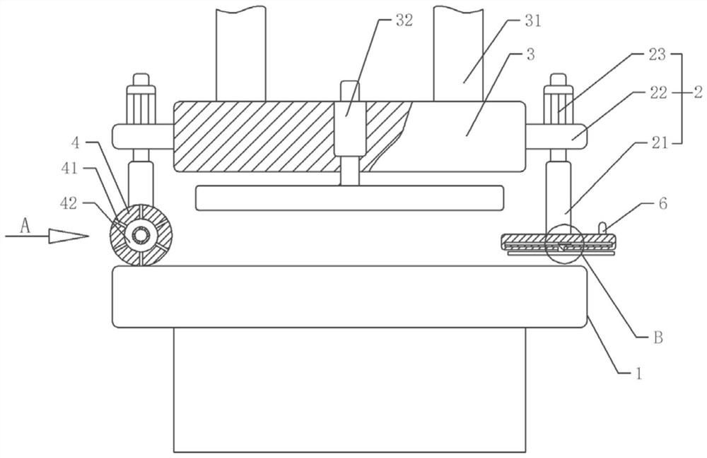
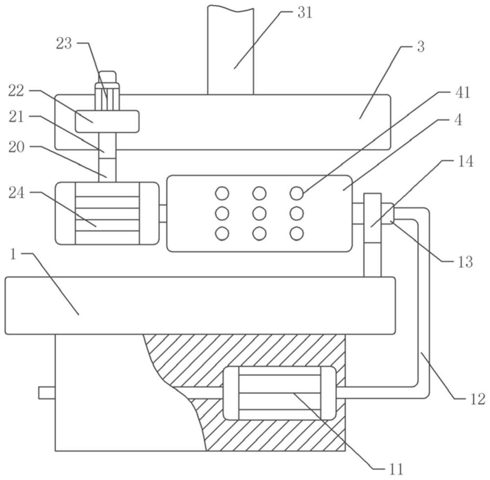
[0039] Basic as attached figure 1 , attached figure 2 And attached image 3 As shown, a steel plate straightening device includes a frame, a placement platform 1 and a hydraulic mechanism located above the placement platform 1. The hydraulic mechanism includes a first hydraulic cylinder 31 and a moving plate fixed on the output shaft of the first hydraulic cylinder 31 by bolts. 3.

[0040] The moving plate 3 is provided with a straightening mechanism, and the straightening mechanism includes a driver bolted on the moving plate 3. In this embodiment, the driving piece is the third hydraulic cylinder 32, and the output shaft of the third hydraulic cylinder 32 is bolted with a Alignment board. Both sides of the moving plate 3 are provided with an adjusting mechanism 2, the adjusting mechanism 2 includes an adjusting plate 22 bolted on the moving plate 3, the adjusting plate 22 is bolted with a second hydraulic cylinder 23, and the output shaft of the second hydraulic cylinder...

Embodiment 2

[0049] The difference between embodiment two and embodiment one is that, as attached Figure 5 As shown, a recovery box 71 is provided on one side of the placement table 1, and the recovery box 71 is filled with a dedusting solution. In this embodiment, the dedusting solution is water. The bottom bolt of recovery box 71 is fixed with intake check valve 72, and the air outlet of negative pressure pump 11 is communicated with intake check valve 72 by pipeline, and the top of recovery box 71 has gas port, and gas port is communicated with gas storage box 75. Connected air outlet pipe 73, gas storage box 75 bolts are fixed on the placement table 1, and the gas storage box 75 is communicated with a valve, and the valve bolt is fixed on the gas storage box 75 (not shown), and the valve is connected with the shower nozzle 74.

[0050] The specific implementation process is as follows:

[0051] The negative pressure pump 11 enters the gas in the leveling roller 4 into the water throu...


PUM


Abstract

The invention relates to the technical field of steel plate straightening, and discloses a steel plate straightening device, which includes a machine frame, a placement platform and a hydraulic mechanism located above the placement platform. The hydraulic mechanism is provided with a straightening mechanism, and the straightening mechanism includes a driving part and a The straightening plate on the output shaft of the driving part; the two sides of the hydraulic mechanism are respectively provided with adjustment mechanisms, the adjustment mechanism located at the front end of the steel plate transportation direction is provided with a leveling mechanism, and the adjustment mechanism located at the rear end of the steel plate transportation direction is provided with a detection mechanism; The leveling mechanism includes a power part vertically slidably connected with the frame and a leveling roller fixed on the output shaft of the power part, and a telescopic shaft is fixed on the placing table, and the telescopic section of the telescopic shaft is rotatably connected with the leveling roller. The invention has a simple structure and can straighten the steel plate multiple times, thereby improving the straightening quality of the steel plate.

Description

technical field [0001] The invention relates to the technical field of steel plate straightening, in particular to a steel plate straightening device. Background technique [0002] Light poles, as the name suggests, are poles for installing street lights, which can be called light poles. Light poles are divided into: iron light poles, stainless steel light poles, and aluminum alloy light poles. Most of our country is dominated by iron light poles. [0003] During the manufacturing process of the street light pole, the operator bends the steel plate into a cylindrical shape through a bending machine to form the preliminary shape of the street light pole. During the placement process, the steel plate will be affected by the external environment or external impact to a certain degree of deformation, which will cause the steel plate to be bent into a cylindrical shape. Straightening the steel plate to improve the quality of the cylindrical steel plate. [0004] In the prior ar...

Claims


Application Information

Patent Timeline
Patent Type & Authority Patents(China)
IPC IPC(8): B21D1/02B08B5/02B21C51/00
CPCB08B5/02B21C51/00B21D1/02
Inventor 赵长刚
Owner 重庆市荣昌区永世光电设备有限公司
Why Eureka
Try Eureka