Coal mine underground micro-seismic monitoring sensor arrangement method based on P-wave incident direction

A technology for incident direction and microseismic monitoring, applied in seismology, mining equipment, mining equipment and other directions for logging records, can solve the problems of inconsistency, inability to give, and not considered in engineering, to improve monitoring accuracy and, Guaranteed effect of space layout, simplified modeling and calculation process

Active Publication Date: 2020-06-19
SOUTHWEST UNIVERSITY
View PDF6 Cites 7 Cited by
  • Summary
  • Abstract
  • Description
  • Claims
  • Application Information

AI Technical Summary

Problems solved by technology
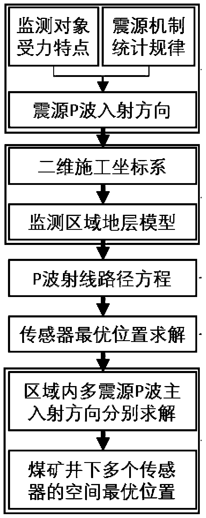
[0004] However, these current methods have the following drawbacks: (1) Qualitative analysis only plans the sensor deployment area from a macro perspective, and cannot give specific coordinates that can be directly used for on-site installation; (2) The core of the current theoretical algorithm is In the ideal environment of homogeneous medium or constant wave velocity, relying on the covariance matrix related to the source parameters and sensor position parameters in the network optimization objective function, the sensor position parameters are solved
Obviously, these algorithms do not take into account the influence of the horizontal layered strata of the coal mine, which is inconsistent with the actual engineering

Method used


Image

  • Coal mine underground micro-seismic monitoring sensor arrangement method based on P-wave incident direction
  • Coal mine underground micro-seismic monitoring sensor arrangement method based on P-wave incident direction
  • Coal mine underground micro-seismic monitoring sensor arrangement method based on P-wave incident direction

Examples


Embodiment 1

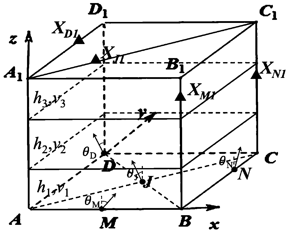
[0047] (1) There is a risk of roof fall in the next area of ​​a coal mine. In order to ensure the safety of underground mining, it is planned to introduce a microseismic monitoring system to monitor the area. The first batch is planned to be in the cube area A with side length of 100m 1 B 1 C 1 D. 1 - 4 sensors are installed on the boundary of ABCD, and now it is necessary to optimize the design of the positions of the 4 sensors.

[0048] (2) According to the force characteristics of the monitoring objects and the statistical laws of the source mechanism characteristics in the monitoring area, the main incident direction of the P wave of each source in the monitoring area is preliminarily judged as follows: image 3 As shown, the incident point can be represented by D, and the incident angle θ D = 30°. The direction of incidence belongs to the plane A in the vertical direction 1 D. 1 DA belongs to the plane ABCD in the horizontal direction.

[0049] (3) The construction...


PUM


Abstract

The invention provides a coal mine underground micro-seismic monitoring sensor arrangement method based on a P-wave incident direction, and belongs to the technical field of coal mine underground safety monitoring. The method comprises the following steps: determining a P-wave main incident direction of a micro-seismic event in a monitoring area according to a stress characteristic of a monitoringobject and a seismic source mechanism characteristic statistical law in the monitoring area; then establishing a two-dimensional area construction coordinate system and a layered stratum model conforming to geological characteristics of the monitoring area, and further establishing a ray path equation of P waves; substituting ray parameters, stratum parameters, wave velocity parameters and the like into a ray equation in sequence to obtain the optimal position of sensor arrangement in a coal seam medium; and finally, sequentially solving the sensor positions corresponding to other main incident directions of the P waves of all seismic sources in the monitoring area, and using the sensor positions as the optimal arrangement positions of the sensors in the three-dimensional monitoring area.The method is simple in calculation and accurate in result, and can be suitable for the design of the optimal position of the micro-seismic monitoring sensor of horizontal layered medium undergroundengineering such as coal mines.

Description

technical field [0001] The invention relates to the technical field of underground safety monitoring in coal mines, in particular to a method for arranging microseismic monitoring sensors in underground coal mines based on the incident direction of P waves. Background technique [0002] Geological disasters such as coal mine rock burst and coal and gas outburst have seriously affected the safe mining of coal resources. In recent years, the microseismic monitoring technology evolved and developed from the seismic exploration industry has been widely used, such as Shandong Liangbaosi Coal Mine, Shanxi Pingmei Coal Mine No. 1, Henan Yima Coal Mine, etc. The reasonable spatial layout of the microseismic monitoring sensor network is the prerequisite for the stable operation and reliable data of the microseismic monitoring system. These in turn determine the distribution law and energy of underground rock burst, the accuracy of safety assessments such as coal and gas outburst str...

Claims


Application Information

Patent Timeline
Patent Type & Authority Applications(China)
IPC IPC(8): G01V1/40E21F17/18
CPCG01V1/40E21F17/18
Inventor 吴庆良吴梦军刘新荣冯礼赵丙辰
Owner SOUTHWEST UNIVERSITY
Why Eureka
Try Eureka