Rotating device

A technology for rotating equipment and aligning sheets, which is applied in the directions of electromechanical devices, casings/covers/supports, electrical components, etc., and can solve the problems of cumbersome, cumbersome assembly, and insufficient simplification of operations.

Pending Publication Date: 2020-07-07
MINEBEA CO LTD
View PDF1 Cites 0 Cited by
  • Summary
  • Abstract
  • Description
  • Claims
  • Application Information

AI Technical Summary

Problems solved by technology

However, in an airtight container, since the through hole for installation cannot be provided in the casing, installation becomes cumbersome or requires a space for installation.
For example, if a belt-shaped pressing member such as metal is wound around the motor and its ends are fastened, a space for the fastening is required, and in addition, this work becomes cumbersome, resulting in an increase in cost
[0004] In addition, if the flange is provided in advance on the motor and the flange is fastened, a space for fastening is still required, and the simplification of work is not sufficient.
Therefore, if the motor is firmly mounted on the case, not only is it difficult to reduce the size of the airtight container, but also special processing is required or the number of parts for mounting increases, resulting in cumbersome assembly and increased cost

Method used


Image

  • Rotating device
  • Rotating device
  • Rotating device

Examples


Embodiment Construction

[0030] Hereinafter, embodiments of the present invention will be described with reference to the drawings.

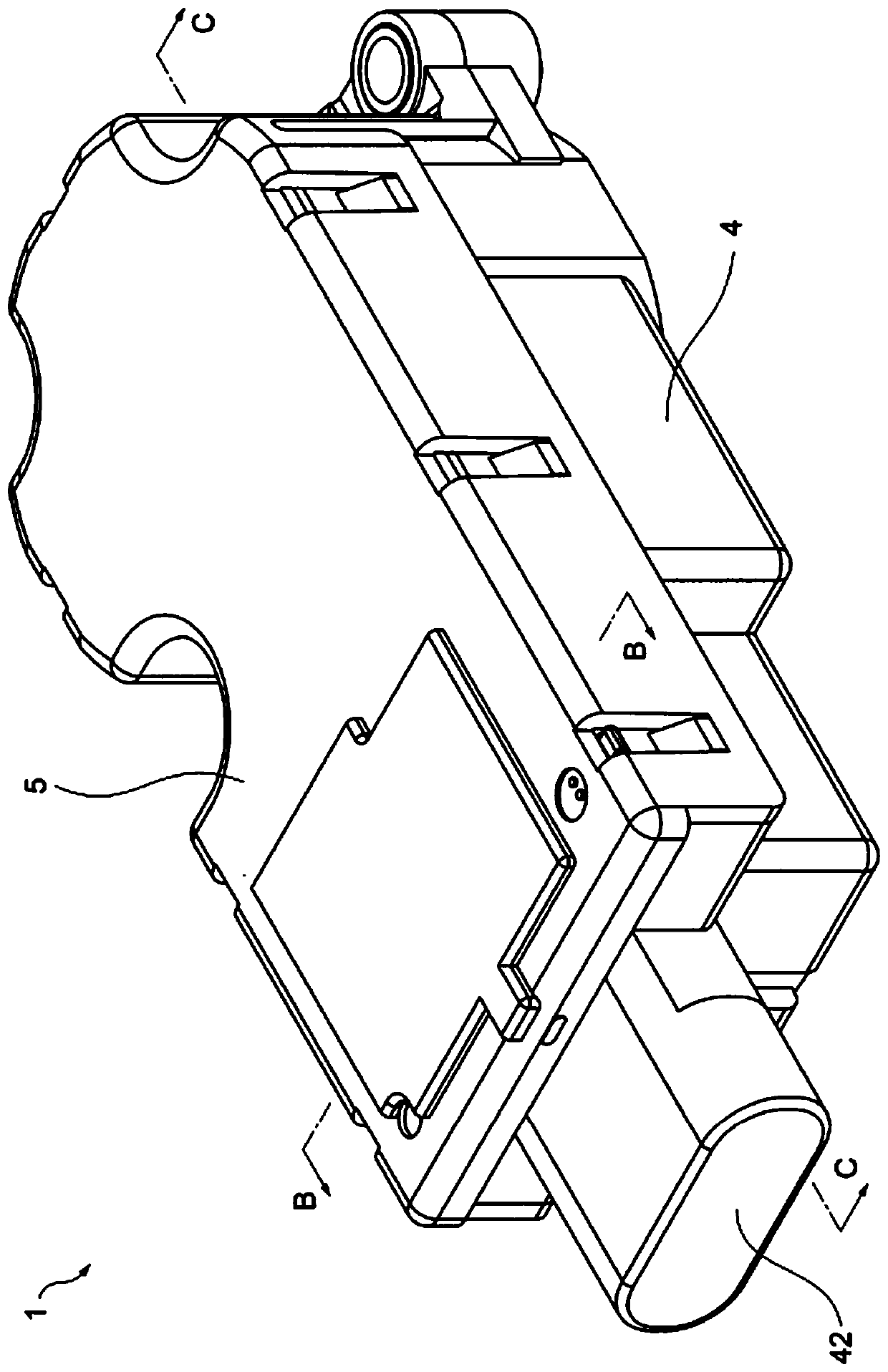
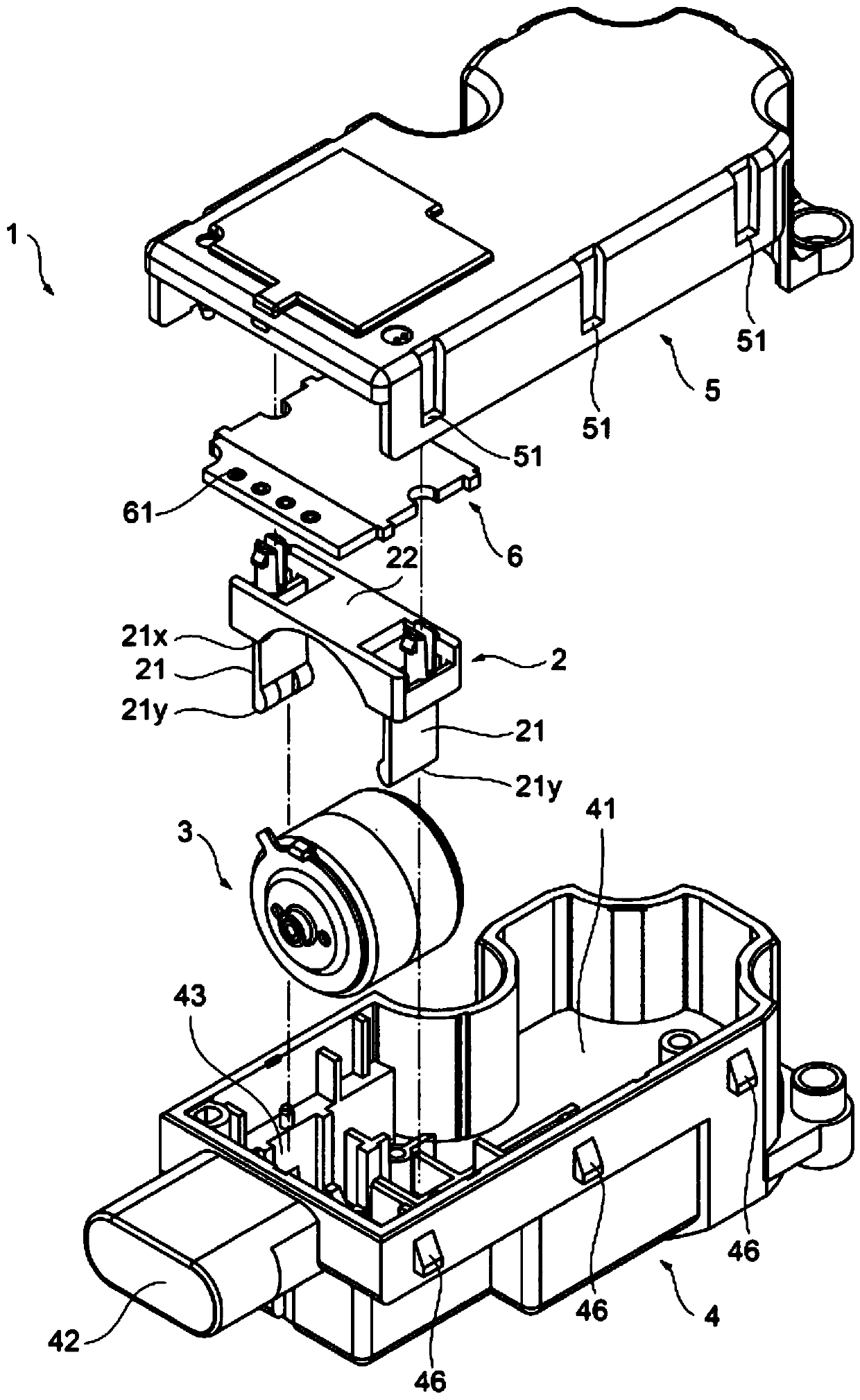
[0031] figure 1 It is a perspective view of a rotating device according to an embodiment as an example of the present invention, figure 2 It is an exploded perspective view. In addition, in figure 2 In FIG. 2 , some components accommodated in the case 4 are not directly related to the configuration of the present invention, so illustration is omitted (the same applies to subsequent drawings). Actually, a reduction gear set and the like for decelerating the rotational driving force of the motor 3 are also accommodated in the casing 4 for outputting the required rotational driving force to the outside.

[0032] The rotary device 1 is configured by accommodating a motor 3 in an airtight container composed of a case 4 with one surface open and a cover 5 combined to cover the opening. In this embodiment, the motor 3 is held using the holder 2 and the wiring board 6 is ...


PUM


Abstract

The invention provides a rotating device which does not need space, is simple in structure, and enables a motor to be firmly installed on a housing. The rotating device is provided with: a holder (2)having a pair of pieces (21, 21) and a main body (22); a motor (3) sandwiched between the pair of pieces (21, 21); and a housing (4) that houses the motor (3) sandwiched between the pair of pieces (21, 21), the housing (4) being provided with a pressing part (43) by which the pair of pieces (21, 21) sandwiching the motor (3) are pressed toward the motor (3) side.

Description

technical field [0001] The present invention relates to a rotary device that includes a motor and supplies rotational driving force to various devices. Background technique [0002] Conventionally, various types of motors have been used to supply rotational driving force to various devices. Motors are electrical components, so keep them away from moisture and dust. However, electric equipment of automobiles used outdoors may be difficult to avoid moisture and dust due to the environment in which they are used. In such an environment, the motor is used with the motor housed in an airtight container. [0003] Since the motor generates driving force, it is required to be firmly fixed to the housing. However, in an airtight container, since the through-hole for installation cannot be provided in the case, installation becomes cumbersome or a space for installation is required. For example, if a belt-shaped pressing member such as metal is wound around the motor and its ends a...

Claims


Application Information

Patent Timeline
Patent Type & Authority Applications(China)
IPC IPC(8): H02K5/04H02K5/22H02K5/24H02K7/10H02K7/116
CPCH02K5/04H02K5/22H02K5/24H02K7/10H02K7/116H02K5/225H02K5/10
Inventor 松野武北川智之加藤柊史
Owner MINEBEA CO LTD
Why Eureka
Try Eureka