Battery charging and discharging control circuit

A charging and discharging control and charging control technology, applied in the electronic field, can solve problems such as easy heating and low battery charging efficiency

Active Publication Date: 2020-08-18
SHENZHEN ICM MICROELECTRONICS CO LTD
View PDF5 Cites 1 Cited by
  • Summary
  • Abstract
  • Description
  • Claims
  • Application Information

AI Technical Summary

Problems solved by technology

[0011] The invention provides a battery charge and discharge control circuit to solve the problems of low batter

Method used


Image

  • Battery charging and discharging control circuit
  • Battery charging and discharging control circuit
  • Battery charging and discharging control circuit

Examples


Embodiment Construction

[0070] In order to make the object, technical solution and advantages of the present invention clearer, the present invention will be further described in detail below in conjunction with the accompanying drawings and embodiments. It should be understood that the specific embodiments described here are only used to explain the present invention, not to limit the present invention.

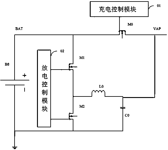
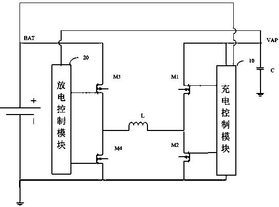
[0071] The battery charging and discharging control circuit provided by the present invention adds a power transistor and combines a switching charging and discharging mode on the basis of the prior art. When the input and output interface of the battery charging and discharging control circuit is connected to the adapter, the charging control module controls the on and off of the first power transistor and the second power transistor according to the charging current, so as to charge the battery Perform constant current charging, and control the on and off of the first power transistor and the sec...


PUM


Abstract

The invention relates to the technical field of electronics, and provides a battery charging and discharging control circuit. The circuit comprises a charging control module, a capacitor, a first power transistor, a second power transistor, an inductor, a third power transistor, a fourth power transistor and a discharging control module, wherein the charging control module is used for detecting and controlling the on and off of the first power transistor and the second power transistor according to the charging current when the charging control module is connected with the adapter so as to perform constant-current charging on the battery; and detecting and controlling on and off of the first power transistor and the second power transistor according to the battery voltage so as to performconstant-voltage charging on the battery. The discharge control module is used for detecting and controlling the connection and disconnection of the third power transistor and the fourth power transistor according to the discharge voltage when the discharge control module is connected with electric equipment or floats, so the discharge voltage is kept stable. According to the invention, the problems of low battery charging efficiency and easy heating when a drive-by-wire control mode is adopted for charging in the prior art are solved.

Description

technical field [0001] The invention relates to the field of electronic technology, in particular to a battery charging and discharging control circuit. Background technique [0002] In the field of 1.5V power supply, the prior art mainly uses disposable batteries. However, disposable batteries have serious environmental pollution problems and cannot be reused. In order to solve this problem, it is imminent to use rechargeable and energy-saving and environmentally friendly batteries to replace disposable batteries, and the method has also emerged as the times require. [0003] figure 1 It is a basic structural block diagram of an existing battery charge and discharge control circuit. like figure 1 As shown, the battery charge and discharge control circuit includes a rechargeable battery B0, a power transistor M0, a power transistor M1, a power transistor M2, an energy storage inductor L0, a filter capacitor C0, an input and output interface VAP, a charging control module...

Claims


Application Information

Patent Timeline
IPC IPC(8): H02J7/00
CPCH02J7/0063
Inventor 李杰白青刚杨小华
Owner SHENZHEN ICM MICROELECTRONICS CO LTD
Why Eureka
Try Eureka