Drive unit box

An accessory transmission and centrifugal technology, applied in transmission parts, crankcase ventilation, engine components, etc., can solve problems such as inability to compactly locate adjacent units, increase AGB outline size and weight, and large footprint

Pending Publication Date: 2020-09-11
联合发动机制造集团股份公司
View PDF8 Cites 3 Cited by
  • Summary
  • Abstract
  • Description
  • Claims
  • Application Information

AI Technical Summary

Problems solved by technology

The disadvantage of this prototype is the presence of the centrifugal breather housing (attached to the AGB) which takes up a large footprint along with the fasteners and oil bypass flanges to attach it to the AGB housing , and cannot compactly position adjacent units, increasing the AGB profile size and weight

Method used


Image

  • Drive unit box
  • Drive unit box
  • Drive unit box

Examples


Embodiment Construction

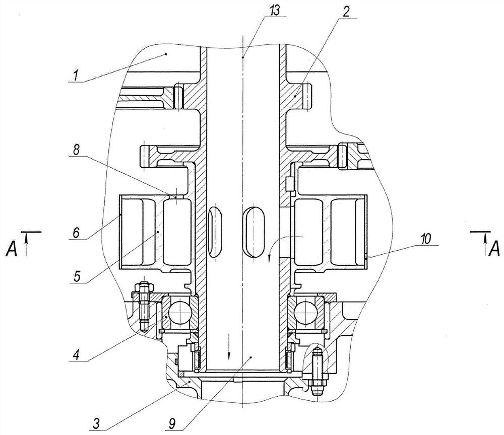
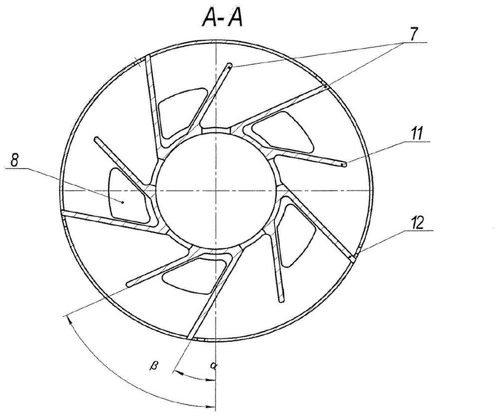
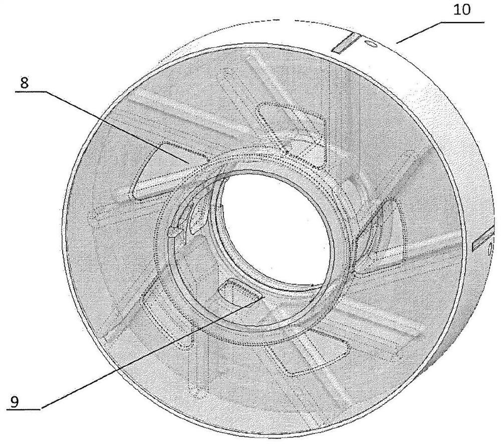
[0015] Accessory gearbox 1 ( figure 1 , figure 2 , image 3 ) contains a gear 2, a branch pipe 3, a bearing 4, a centrifugal impeller 5 with blades 7; the centrifugal impeller contains a casing 6 which can form a cavity, and a window 8 for the inlet of the air-oil mixture, an air outlet window 9 and openings 10 for draining separated oil; the blades 7 of the impeller 5 are made with different lengths 11 , 12 and are positioned at angles α and β with respect to the axis of rotation 13 of the gear 2 .

[0016] The accessory gearbox is designed to operate as follows.

[0017] The centrifugal breather (without position marking) located in the housing 1 of the accessory transmission box contains the gear 2 on which the centrifugal impeller 5 is mounted. The centrifugal impeller has a housing 6 and blades 7 of different lengths 11, 12 positioned at different angles α and β to the axis of the gear 2, which lead to the formation of interconnected adjacent cavities, the windows of ...


PUM


Abstract

The invention relates to the field of aircraft engine manufacture, particularly to aircraft gas turbine engine (GTE) oil system elements. A drive unit box comprises a gear, a nozzle, bearings, and a centrifugal impeller having blades. The centrifugal impeller having blades comprises a cowl adapted for the formation of inner cavities; ports for the intake of a gas-oil mixture and the expulsion of air, and for oil discharge; blades that are of different lengths and are disposed at angles Alpha and Beta relative the axis of rotation of the gear. Furthermore, the centrifugal impeller can compriseblades having a curvilinear form. Furthermore, the centrifugal impeller can comprise at least two consecutively positioned stages for separating oil and air. The design of the proposed invention having the above-indicated characterizing features, in conjunction with known features, allows for improving the assembly process, reducing the dimensions and mass of the drive unit box, and increasing theefficiency of oil separation.

Description

technical field [0001] The invention relates to the field of aero-engine manufacturing, in particular to components of a gas turbine engine (GTE) lubrication system. Background technique [0002] The design of a centrifugal respirator comprising a housing with an axial impeller is known (patent RU NO. 2551454 published on May 27, 2015, IPC F02C7 / 06). A disadvantage of the known breather is that the external location of the centrifugal breather housing and the fasteners attaching it to the accessory transmission case and bypass oil valve take up a significant amount of floor space and do not allow for compact placement of adjacent units , thereby increasing the size and weight of the accessory gearbox (AGB). Additionally, the presence of the oil adjustment threads in the respirator housing increases factory labor time and manufacturing costs. [0003] The design of a centrifugal respirator comprising a gear mounted impeller is also known (RU Patent No. 2548228 published on ...

Claims


Application Information

Patent Timeline
Patent Type & Authority Applications(China)
IPC IPC(8): F02C7/06F01M11/08
CPCF02C7/06F02C7/32F05D2240/70F05D2260/609F16H57/027F16H57/0402F01M13/04F01M2013/0422F16N39/002F16N2210/02Y02T50/60
Inventor K·A·斯蒂亚日科夫R·Z·哈萨诺夫A·V·契尔科夫
Owner 联合发动机制造集团股份公司
Why Eureka
Try Eureka