Dye filtering device for textile production

A filter device and dye technology, which is applied in the field of textile production, can solve the problems of dye filter influence, device blockage, etc., and achieve the effect of improving filter efficiency

Inactive Publication Date: 2020-09-29
诸暨市众创机械设备厂
View PDF11 Cites 5 Cited by
  • Summary
  • Abstract
  • Description
  • Claims
  • Application Information

AI Technical Summary

Problems solved by technology

A filter device for acid dye production in the above-mentioned patent has the following disadvantages: when the dye is filtered, because the dye is doped with impurities, the existing device may be damaged due to impurities when the dye is filtered. Clogging the interior of the device, which affects the filtration of the dye

Method used


Image

  • Dye filtering device for textile production
  • Dye filtering device for textile production
  • Dye filtering device for textile production

Examples


Embodiment 1

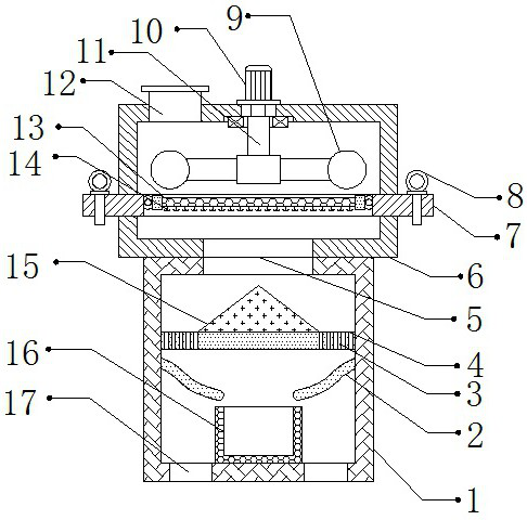
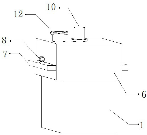
[0026] refer to Figure 1-2 , a dye filter device for textile production, comprising a stirring box 6, a feed pipe 12 is arranged on one side of the top outer wall of the stirring box 6, a rotating shaft 11 is rotatably connected to the top inner wall of the stirring box 6 through a bearing, and the bottom outer wall of the rotating shaft 11 The stirring shaft 9 is connected by bolts, the top outer wall of the stirring box 6 is connected with a motor 10 by bolts, and one end of the output shaft of the motor 10 is connected with the rotating shaft 11 by bolts, the outer walls of both sides of the stirring box 6 are provided with sockets, and A pull-out plate 7 is plugged between the two sockets, jacks are provided on both sides of the top outer wall of the draw-out plate 7, and a latch 8 is plugged into the inner walls of the two jacks, and the top outer wall of the pull-out plate 7 is provided with There is a fixed opening, and the inner wall of the fixed opening is connected ...

Embodiment 2

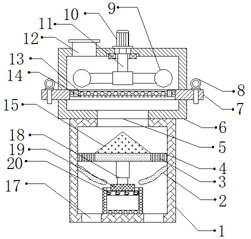
[0030] refer to image 3 , a dye filter device for textile production. Compared with Embodiment 1, the bottom outer wall of the support plate 3 is connected with an electric telescopic rod 18 by bolts, and the bottom outer wall of the electric telescopic rod 18 is connected with a pressure plate 19 by bolts. A cotton block 20 is bonded to the bottom outer wall of the pressing plate 19 .

[0031] Working principle: when in use, the dye is filled into the stirring box 6 through the feed pipe 12, the motor 10 is started, and the motor 10 will drive the rotating shaft 11 to rotate, so that the dye is stirred through the stirring shaft 9, and the dye is passed through the filter 13 The dye is filtered, and at the same time, the barb 14 can be used to clean up the floating matter doped in the dye, so as to prevent the floating matter doped inside the dye from affecting the filtration of the dye, and the filtered dye will enter through the port 5 into the Inside the filter box 1, th...


PUM


Abstract

The invention discloses a dye filtering device for textile production. The dye filtering device comprises a stirring box, wherein a feeding pipe is arranged on one side of the outer wall of the top ofthe stirring box; the inner wall of the top of the stirring box is rotationally connected with a rotating shaft through a bearing; a stirring shaft is fixedly connected to the outer wall of the bottom of the rotating shaft; the outer wall of the top of the stirring box is fixedly connected with a motor; one end of motor output shaft is connected with rotating shaft through bolts; inserting openings are formed in the outer walls of the two sides of the stirring box correspondingly; a drawing plate is arranged between and connected with the two inserting openings in an inserted mode; insertingholes are formed in the two sides of the outer wall of the top of the drawing plate correspondingly; and inserting pins are connected to the inner walls of the two inserting holes in an inserted mode.The dye filtering device can prevent the surface of a filter screen from being blocked by impurities doped in dye, prevent floaters from being doped in the dye to influence the filtering of the dye and filter the dye in a filter barrel through extrusion, and is improved in dye filtering efficiency.

Description

technical field [0001] The invention relates to the technical field of textile production, in particular to a dye filter device for textile production. Background technique [0002] Textile is a handicraft industry that serves human clothing. During textile production, dyes need to be filtered through filter devices. [0003] After searching, the Chinese patent authorization number is CN209333274U, which discloses a filter device for the production of acid dyes, including a device main body, a storage room is arranged at the inner lower position of the device main body, and the inner upper position of the device main body is There is a stirring chamber at the place, and the filter device for acid dye production is equipped with a water pump, a suction pipe and a feed pipe. When the user uses this filter device to filter the acid dye, the acid dye can be added to the In the mixing chamber, the acid dye is filtered through the filter screen and then enters the storage chamber...

Claims


Application Information

Patent Timeline
Patent Type & Authority Applications(China)
IPC IPC(8): B01D29/58B01D29/96B01D36/02
CPCB01D29/58B01D29/96B01D36/02
Inventor 刘欢红
Owner 诸暨市众创机械设备厂
Why Eureka
Try Eureka