Boiler bottom through-wall expansion joint

An expansion joint and wall penetration technology, which is applied to expansion compensation devices for pipelines, thermal insulation, pipes, etc., can solve problems such as cracking, gradual collapse, and difficulty in thermal insulation of pipelines.

Pending Publication Date: 2020-10-30
诸暨市沣泽动力机械有限公司
View PDF0 Cites 2 Cited by
  • Summary
  • Abstract
  • Description
  • Claims
  • Application Information

AI Technical Summary

Problems solved by technology

[0002] The high-temperature hot gas of the waste heat boiler of the gas turbine power plant is transported from the bottom to the external area for reuse. When installing the wall, because the temperature of the pipe is high, in order to avoid the hidden danger of cracking or even gradual collapse caused by the high-temperature baking of the wall, at the same time, the thermal expansion and contraction of the pipe will drive the wall to move at the same time. Therefore, in practical applications, the high-temperature pipe should not be in direct contact with the wall , A circular hole with a diameter several centimeters larger than the high-temperature pipe is usually reserved on the wall. It is not easy to operate the pipe outsourcing insulation material; 2: The gap between the reserved wall hole and the pipe is not easy to close

Method used


Image

  • Boiler bottom through-wall expansion joint
  • Boiler bottom through-wall expansion joint
  • Boiler bottom through-wall expansion joint

Examples


Embodiment Construction

[0020] The technical solutions of the present invention will be further specifically described below through the embodiments and in conjunction with the accompanying drawings.

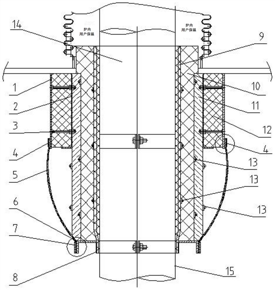
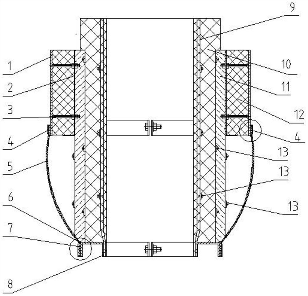
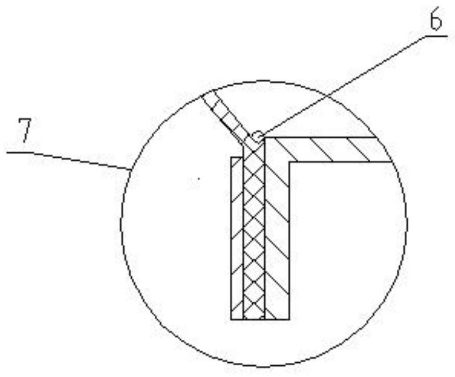
[0021] Such as figure 1 , figure 2 , image 3 As shown, a furnace bottom wall-penetrating expansion joint is used for the wall-penetrating connection of the waste heat boiler furnace bottom. The connecting pipe 1 and the thermal insulation liner 2 are filled with a fixed thermal insulation layer 4 12, and a number of studs 3 evenly distributed around the circumference are used. The connection is fixed in one piece, the strength is high, and the stress absorption is uniform, and it has a good heat preservation function.

[0022] The inner circle of the thermal insulation liner 2 is sequentially stacked with a fixed thermal insulation layer three 11, a fixed thermal insulation layer two 10 and a fixed thermal insulation layer one 9, and each adjacent fixed thermal insulation layer is fixed with a fast...


PUM


Abstract

The invention discloses a boiler bottom through-wall expansion joint. The boiler bottom through-wall expansion joint is used for pipeline through-wall heat insulation and displacement offsetting of awaste heat boiler bottom. The space between a connecting pipe and a heat insulation liner plate on the inner side is filled with a forth fixed heat insulation layer, and the connecting plate, the heatinsulation liner plate and the fourth fixed heat insulation layer are connected and fixed integrally through double-screw bolts. A third fixed heat insulation layer, a second fixed heat insulation layer and a first fixed heat insulation layer are sequentially stacked on the inner circle of the heat insulation liner plate, the positions are fixed through tightening steel belts, and the lower endsof the first fixed heat insulation layer, the second fixed heat insulation layer and the third fixed heat insulation layer stretch downwards to be placed on a tabletop of a frame at the lower end. Theupper end of an arched arc telescopic body and a first connecting sleeve are sleeved and surrounded and fastened through a first hoop, the lower end of the arched arc telescopic body and the frame are connected and fastened through a second hoop, and anti-falling rings are arranged at the joints of the upper end and the lower end of the telescopic body for axial position limiting. The boiler bottom through-wall expansion joint is used for waste heat boiler bottom through-wall connection, displacement generated by the waste heat boiler bottom due to high temperature is effectively absorbed, agood heat insulation function is achieved, and the accidents of cracking and even collapsing caused due to the fact that a wall is heated are avoided.

Description

technical field [0001] The invention relates to the technical field of electric equipment, in particular to a furnace bottom wall-penetrating expansion joint. Background technique [0002] The high-temperature hot gas of the waste heat boiler of the gas turbine power plant is transported from the bottom to the external area for reuse. When installing the wall, because the temperature of the pipe is high, in order to avoid the hidden danger of cracking or even gradual collapse caused by the high-temperature baking of the wall, at the same time, the thermal expansion and contraction of the pipe will drive the wall to move at the same time. Therefore, in practical applications, the high-temperature pipe should not be in direct contact with the wall , A circular hole with a diameter several centimeters larger than the high-temperature pipe is usually reserved on the wall. It is not easy to operate the outsourcing insulation material of the pipeline; 2: The gap between the reser...

Claims


Application Information

Patent Timeline
Patent Type & Authority Applications(China)
IPC IPC(8): F16L5/00F16L51/02F16L59/21
CPCF16L5/00F16L51/02F16L59/21
Inventor 陈晓军俞伟学
Owner 诸暨市沣泽动力机械有限公司
Why Eureka
Try Eureka