A self-priming positioning and measuring auxiliary device and its use method

A technology for positioning measurement and auxiliary equipment, which is applied to measuring instruments, measuring devices, measuring inclinations, etc., can solve the problems of poor safety, low operation efficiency, and high labor intensity, so as to prevent safety accidents, improve measurement accuracy and work. Efficiency and manpower saving effect

Active Publication Date: 2022-05-13
CHINA MCC17 GRP
View PDF9 Cites 0 Cited by
  • Summary
  • Abstract
  • Description
  • Claims
  • Application Information

AI Technical Summary

Problems solved by technology

To ensure the accuracy of the "elevation" of the center coordinates of the steel structure, the usual method is: during the hoisting process, people go up to the top of the column and the node of the roof truss, manually find out the intersection point of the center line and then erect the prism. This operation is inefficient and labor-intensive. poor security

Method used


Image

  • A self-priming positioning and measuring auxiliary device and its use method
  • A self-priming positioning and measuring auxiliary device and its use method

Examples


Embodiment 1

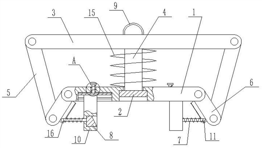
[0029] refer to Figure 1 to Figure 2 As shown, a self-priming positioning and measuring auxiliary equipment includes a fixed plate 1, which is connected with two positioning mechanisms. Connect the adsorption piece 2, a moving plate 3 is arranged above the fixed plate 1, and a connecting piece 4 is fixedly connected to the moving plate 3, and the end of the connecting piece 4 away from the moving plate 3 extends into the stepped hole and is fixedly connected with the absorbing piece 2, moving Both ends of the plate 3 are rotatably connected with a connecting rod 1 5, and the ends of the two connecting rod 1 5 away from the moving plate 3 are rotatably connected with a connecting rod 2 6, and the two connecting rod 2 6 are rotatably connected to the fixed plate 1 respectively. At both ends, two connecting rods 26 are used to drive the corresponding positioning mechanism.

[0030] When the measurement auxiliary equipment is installed, the adsorption part 2 will automatically m...

Embodiment 2

[0045] A method for using a self-priming positioning and measuring auxiliary device, comprising the following steps:

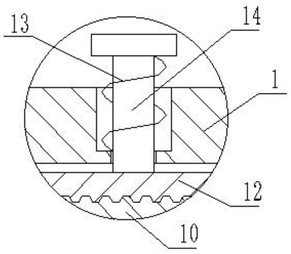
[0046] Step 1: First pull the pull rod 14 upwards, and the pull rod 14 drives the acupressure block 12 to move upward, so that the teeth on the acupressure block 12 and the teeth on the fixed block 10 are separated, and the fixed block 10 is moved to a distance equal to the width of the steel structure ;

[0047] Step 2: Then loosen the pull rod 14, and the pull rod drives the acupressure block 12 to move down under the action of the return spring 2 13, so that the teeth on the acupressure block 12 mesh with the teeth on the fixed block 10, and the fixed block 10 is locked ;

[0048] Step 3: Bolt the connecting rope on the pull ring 9, first place the measurement auxiliary equipment on the steel structure, the adsorption part 2 is fixedly adsorbed on the steel structure, the adsorption part 2 drives the moving plate 3 to move downward, and the moving plate 3 ...


PUM


Abstract

The invention discloses a self-priming positioning and measuring auxiliary equipment and a use method thereof, which belong to the technical field of building measuring equipment. Including the fixed plate, the fixed plate is connected with a positioning mechanism, and the middle part of the fixed plate is provided with a stepped hole with a small top and a large bottom, and the large mouth of the stepped hole is slidingly connected to the adsorption piece. There is a connecting piece, the end of the connecting piece away from the moving plate extends into the stepped hole and is fixedly connected with the absorbing piece, both ends of the moving plate are rotatably connected with a connecting rod one, and the ends of the two connecting rods one away from the moving plate are both rotatably connected There are two connecting rods, and the two connecting rods are connected to the two ends of the fixed plate in rotation respectively, and the two connecting rods are used to drive the positioning mechanism. It greatly improves the measurement accuracy and work efficiency, and can save manpower to achieve the purpose of reducing construction costs, and can effectively prevent safety accidents in the construction process.

Description

technical field [0001] The technical field to which the present invention relates, in particular, relates to a self-priming auxiliary device for positioning and measuring and a method for using it. Background technique [0002] In the construction of sports venues, during the installation of steel columns and roof truss structures, measurement technology is used to effectively control the verticality of the columns. During the construction process, the coordinates of the center of the columns must be strictly controlled, and the coordinate elevation of all roof steel structure nodes must be controlled according to the requirements of the drawings. . To ensure the accuracy of the "elevation" of the center coordinates of the steel structure, the usual method is: during the hoisting process, people go up to the top of the column and the node of the roof truss, manually find out the intersection point of the center line and then erect the prism. This operation is inefficient and...

Claims


Application Information

Patent Timeline
Patent Type & Authority Patents(China)
IPC IPC(8): G01C5/00G01C15/00G01C9/00G01C9/02G01B21/00B66C1/02
CPCG01C5/00G01C15/00G01C9/00G01C9/02G01B21/00B66C1/0256
Inventor 王晓坡王俊凯
Owner CHINA MCC17 GRP
Why Eureka
Try Eureka