A power-cooling combined power supply system for marine gas turbine waste heat recovery

A gas turbine and waste heat recovery technology, applied to heat exchangers, mechanical equipment, indirect heat exchangers, etc., to reduce irreversible losses, improve comfort, and improve overall efficiency

Active Publication Date: 2021-12-21
KUNMING UNIV OF SCI & TECH
View PDF6 Cites 0 Cited by
  • Summary
  • Abstract
  • Description
  • Claims
  • Application Information

AI Technical Summary

Problems solved by technology

[0005] Although there are many international studies on the use of ORC to recover exhaust heat from gas turbines, there are few cases where ORC technology is actually applied to the recovery of waste heat from marine gas turbines.

Method used


Image

  • A power-cooling combined power supply system for marine gas turbine waste heat recovery

Examples


Embodiment 1

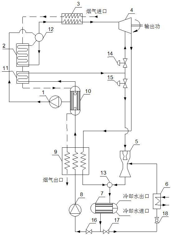
[0022] Such as figure 1As shown, the ship gas turbine waste heat recovery system includes ORC liquid supply pump 1, ORC steam generator 2, ORC superheater 3, ORC turbine 4, ejector 5, refrigeration evaporator 6, and condenser 7. Low-pressure liquid supply pump 8, low-pressure preheater 9, low-pressure steam generator 10, low-pressure superheater 11, steam drum 12, mixer 13, regulating valve, stop valve and throttle valve 18; ship gas turbine flue gas in sequence After passing through the ORC superheater 3, ORC steam generator 2, low-pressure superheater 11, low-pressure steam generator 10 and low-pressure preheater 9, the heat is released from the flue gas outlet of the low-pressure preheater 9; the steam at the top of the low-pressure steam generator 10 The outlet of the working medium is connected to the inlet of the low-pressure superheater 11, and the outlet of the superheated steam working medium of the low-pressure superheater 11 is divided into two routes, one of which ...

Embodiment 2

[0025] Such as figure 1 As shown, the ship gas turbine waste heat recovery system includes ORC liquid supply pump 1, ORC steam generator 2, ORC superheater 3, ORC turbine 4, ejector 5, refrigeration evaporator 6, and condenser 7. Low-pressure liquid supply pump 8, low-pressure preheater 9, low-pressure steam generator 10, low-pressure superheater 11, steam drum 12, mixer 13, regulating valve, stop valve and throttle valve 18; ship gas turbine flue gas in sequence After passing through the ORC superheater 3, ORC steam generator 2, low-pressure superheater 11, low-pressure steam generator 10 and low-pressure preheater 9, the heat is released from the flue gas outlet of the low-pressure preheater 9; the steam at the top of the low-pressure steam generator 10 The outlet of the working medium is connected to the inlet of the low-pressure superheater 11, and the outlet of the superheated steam working medium of the low-pressure superheater 11 is divided into two routes, one of which...

Embodiment 3

[0028] Such as figure 1 As shown, the ship gas turbine waste heat recovery system includes ORC liquid supply pump 1, ORC steam generator 2, ORC superheater 3, ORC turbine 4, ejector 5, refrigeration evaporator 6, and condenser 7. Low-pressure liquid supply pump 8, low-pressure preheater 9, low-pressure steam generator 10, low-pressure superheater 11, steam drum 12, mixer 13, regulating valve, stop valve and throttle valve 18; ship gas turbine flue gas in sequence After passing through the ORC superheater 3, ORC steam generator 2, low-pressure superheater 11, low-pressure steam generator 10 and low-pressure preheater 9, the heat is released from the flue gas outlet of the low-pressure preheater 9; the steam at the top of the low-pressure steam generator 10 The outlet of the working medium is connected to the inlet of the low-pressure superheater 11, and the outlet of the superheated steam working medium of the low-pressure superheater 11 is divided into two routes, one of which...


PUM


Abstract

The invention relates to a power-cooling co-supply system for waste heat recovery of a ship gas turbine, and belongs to the technical field of ships and energy saving. The ship gas turbine waste heat recovery power and cooling system includes ORC liquid supply pump, ORC steam generator, ORC superheater, ORC turbine, ejector, refrigeration evaporator, condenser, low pressure liquid supply pump, low pressure preheating generator, low pressure steam generator, low pressure superheater, steam drum, mixer, regulating valve, shut-off valve and throttle valve. The system makes full use of the characteristics of the temperature-changing phase transition of the zeotropic mixture and the large difference in the thermodynamic properties of the vapor-liquid two-phase in equilibrium to realize the temperature matching of the heat exchange fluid and the "automatic" high-low temperature two-stage circulating working fluid "adaptation", which reduces the total irreversible loss of the system and improves the overall efficiency of the compound cycle.

Description

technical field [0001] The invention relates to a power-cooling co-supply system for waste heat recovery of a ship gas turbine, and belongs to the technical field of ships and energy saving. Background technique [0002] Because gas turbines have the advantages of compact structure, light weight, high power density, high flexibility, fast response time to power demand, short start-up time, less manpower requirements, low emissions and less noise, naval ships are increasingly inclined to use gas turbines as the original motive, not a diesel engine. However, despite the clear advantages of adopting gas turbine technology with new advances in turbomachinery, blade materials, and processes, there are still some disadvantages. Compared with diesel engines, gas turbines generally have a higher exhaust temperature (about 500 °C), resulting in lower thermal efficiency and exergy efficiency of gas turbines, and higher fuel consumption and operating costs. For naval ships, improving...

Claims


Application Information

Patent Timeline
Patent Type & Authority Patents(China)
IPC IPC(8): F01K23/10F01K25/10F28D21/00
CPCF01K23/10F01K25/10F01K25/106F28D21/0014
Inventor 王辉涛毛芸王建军朱道飞徐煜夏禹辰殷旭东王钰璇魏云辉陈丹晖
Owner KUNMING UNIV OF SCI & TECH
Why Eureka
Try Eureka