Camera positioning method based on real object ID label reading and writing

A positioning method and camera technology, which are applied in image analysis, image communication, image data processing and other directions, can solve the problems of inability to track the field operators in time, on-site monitoring and incomplete video information, etc., and achieve broad market prospects and Application value, good generalizability, and easy-to-achieve effects

Pending Publication Date: 2021-03-26
STATE GRID LIAONING ELECTRIC POWER RES INST +2
View PDF7 Cites 0 Cited by
  • Summary
  • Abstract
  • Description
  • Claims
  • Application Information

AI Technical Summary

Problems solved by technology

However, because the on-site operators need to perform multiple operations and move the workplace, it may happen that the control ball cannot track the on-site operators in time, which will cause the problem of incomplete on-site monitoring and video information Appear

Method used


Image

  • Camera positioning method based on real object ID label reading and writing
  • Camera positioning method based on real object ID label reading and writing

Examples


Embodiment 1

[0032] The present invention provides an embodiment, a camera positioning method based on reading and writing physical ID tags. The present invention is a method for real-time positioning and video monitoring of the working positions of operators on the electric power work site by reading and writing physical ID tags. , this method can automatically judge the area where the on-site workers arrive, and track and shoot the on-site workers.

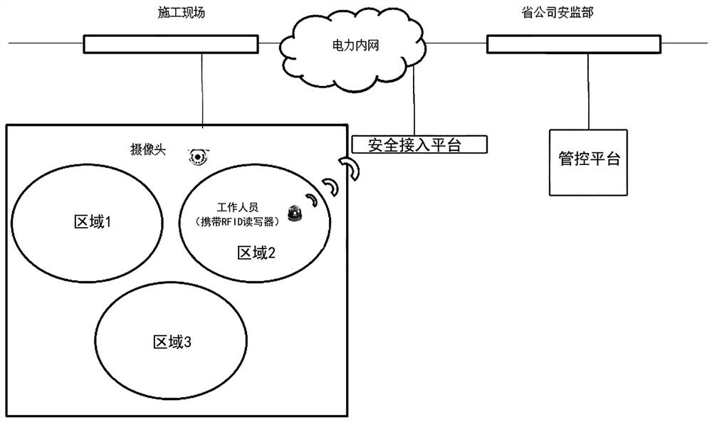
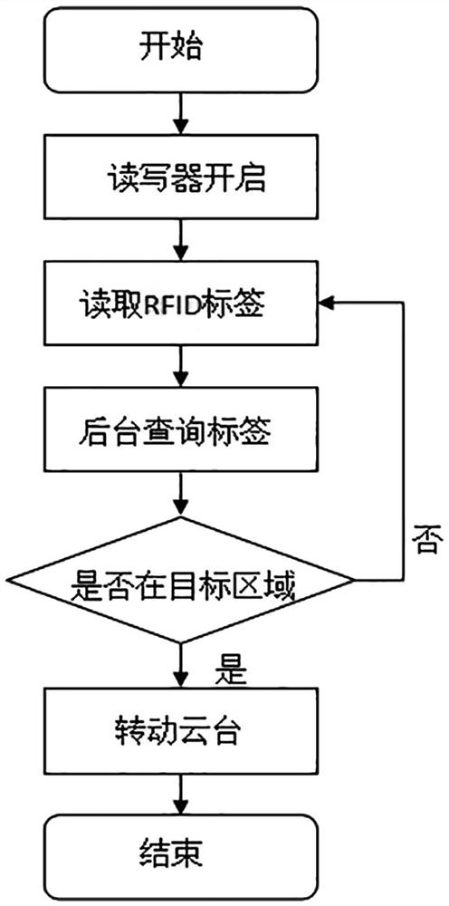
[0033] Such as figure 1 and figure 2 as shown, figure 1 It is the topological structure diagram of the system of the present invention, figure 2 It is a flow chart of the camera positioning method of the present invention.

[0034] The positioning method of the present invention specifically includes the following steps:

[0035] Step 1. According to the work location information in the work ticket, divide the monitoring area and set the camera preset point.

[0036] Before the on-site operators enter the site with work tickets, accor...

Embodiment 2

[0046] The present invention provides an embodiment, a camera positioning method based on physical ID tag reading and writing, specifically as follows:

[0047] Before the on-site workers enter the construction site, they accurately divide the video surveillance target area on the site according to the work location information of the work ticket, and set the camera preset points to correspond to each target area one by one; at the same time, select several physical ID tags in this area, that is, RFID The label serves as the perception point of the area.

[0048] On-site workers are required to wear portable RFID readers when entering the site. The reader / writer has a lock function and cannot be removed at the job site. When the operator wears the reader to enter the field, he will continue to read the physical ID tag, and the read tag information will be connected to the power intranet through the secure access platform and transmitted to the security risk management and con...

Embodiment 3

[0051] Based on the same inventive concept, an embodiment of the present invention also provides a computer storage medium, on which a computer program is stored, and when the computer program is executed by a processor, the physical ID-based The steps of the camera positioning method for tag reading and writing.

[0052] Those skilled in the art should understand that the embodiments of the present application may be provided as methods, systems, or computer program products. Accordingly, the present application may take the form of an entirely hardware embodiment, an entirely software embodiment, or an embodiment combining software and hardware aspects. Furthermore, the present application may take the form of a computer program product embodied on one or more computer-usable storage media (including but not limited to disk storage, CD-ROM, optical storage, etc.) having computer-usable program code embodied therein.


PUM


Abstract

The invention belongs to the technical field of visual intelligent online monitoring, and particularly relates to a camera positioning method based on real object ID label reading and writing. The method comprises the following steps: dividing a monitoring area and setting a camera preset point location according to work place information in a work ticket; using a portable RFID reader-writer as asensing front end for sensing, positioning and tracking; positioning the operation position of an operator through a risk management and control platform; and according to the positioning result of the platform for the operation position of the operator, calling the camera to carry out real-time monitoring. According to the method, the real object ID tags arranged on the power assets in the stategrid real object ID project are reused, the method is simple and easy to implement, and manpower and material resources can be greatly saved. Wide market prospects and application values are realized.The method can effectively track and monitor the on-site operation condition, guarantees no monitoring dead angle, guarantees that the on-site safety management and control is realized, is wider in application range, and can be applied to various scenes of the on-line monitoring of the power transmission and transformation video.

Description

technical field [0001] The invention belongs to the technical field of visual intelligent online monitoring, and in particular relates to a camera positioning method based on physical ID tag reading and writing. Background technique [0002] The video monitoring system is widely used in the field of online monitoring of power transmission and transformation. Based on the actual consideration of the safety risk management and control platform of the Liaoning Provincial Company in the work, at the work site, the site will be monitored by a fixed camera or a control ball placed on the site. Workers monitor. However, because the on-site operators need to perform multiple operations and move the workplace, it may happen that the control ball cannot track the on-site operators in time, which will cause the problem of incomplete on-site monitoring and video information Appear. Contents of the invention [0003] Aiming at the deficiencies in the above-mentioned prior art, the pr...

Claims


Application Information

Patent Timeline
Patent Type & Authority Applications(China)
IPC IPC(8): H04N7/18G06T7/20G06K17/00G06F16/2455H04N5/232
CPCH04N7/18G06T7/20G06K17/0029G06F16/2455H04N23/61
Inventor 付东高强聂盛伟于存湛田野程大伟于淼解飞
Owner STATE GRID LIAONING ELECTRIC POWER RES INST
Why Eureka
Try Eureka