Light path structure and method for inclined projection picture and offset projection picture

A technology of oblique projection and projection device, applied in the field of projectors, can solve problems such as cannot be easily realized, and achieve the effects of preventing position shaking, easily realizing picture tilt and offset, and simple modification and production.

Pending Publication Date: 2021-06-11
深圳铭栋光电科技有限公司
View PDF6 Cites 0 Cited by
  • Summary
  • Abstract
  • Description
  • Claims
  • Application Information

AI Technical Summary

Problems solved by technology

[0002] In order to achieve flexible projection screen display in 3D scanning, it is often necessary to offset or tilt the projection screen. In traditional projection light machines, to achieve this purpose, the display chip needs to be tilted or offset to achieve screen tilt or offset. The purpose of this structure is to tilt or modify the main part of the illumination light path o

Method used


Image

  • Light path structure and method for inclined projection picture and offset projection picture
  • Light path structure and method for inclined projection picture and offset projection picture
  • Light path structure and method for inclined projection picture and offset projection picture

Examples


Example Embodiment

[0030] The following will clearly and completely describe the technical solutions in the embodiments of the present invention with reference to the accompanying drawings in the embodiments of the present invention. Obviously, the described embodiments are only some, not all, embodiments of the present invention. Based on the embodiments of the present invention, all other embodiments obtained by persons of ordinary skill in the art without making creative efforts belong to the protection scope of the present invention.

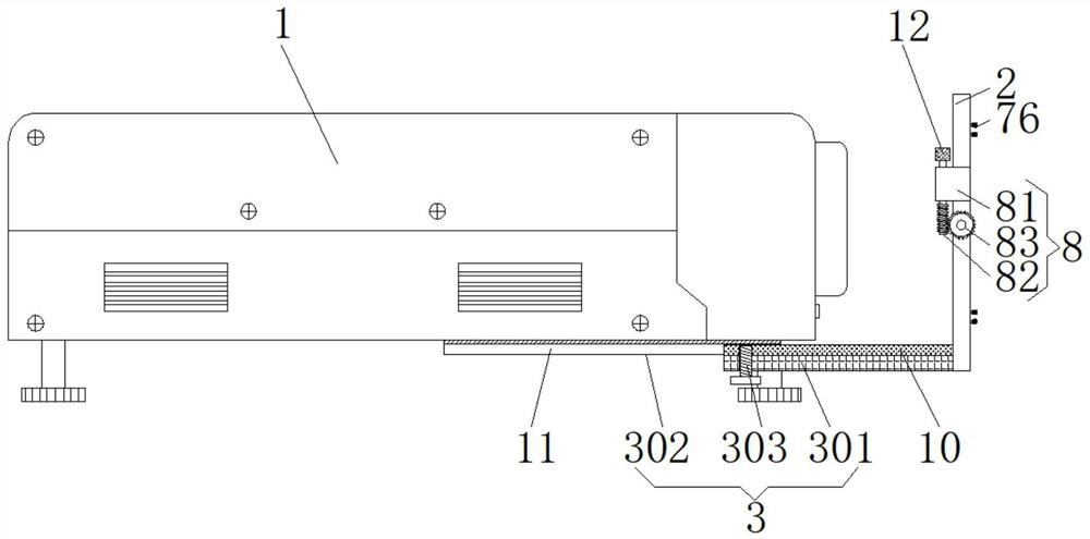
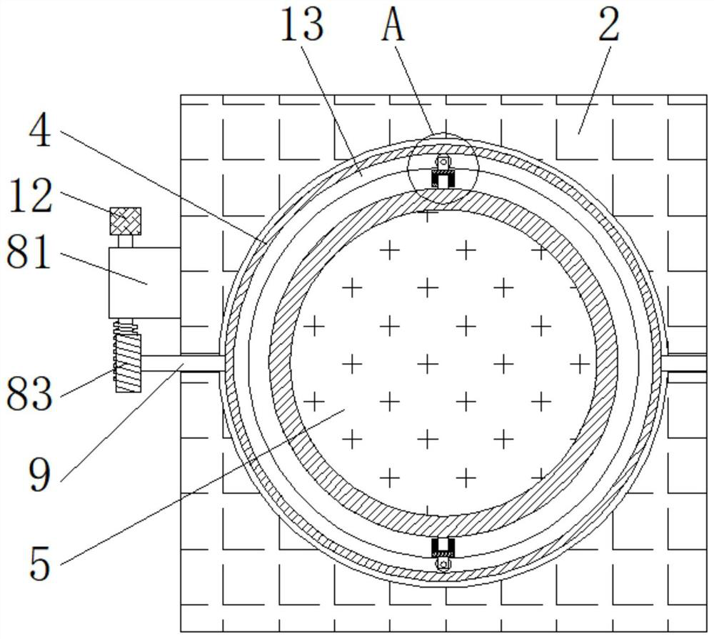
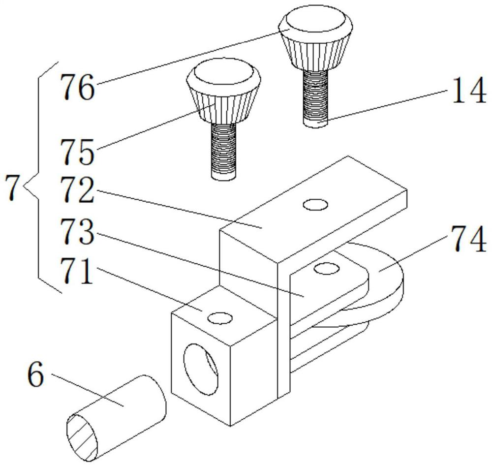
[0031] like Figure 1 to Figure 7 As shown, the present invention provides an optical path structure and method for oblique projection screens and offset projection screens. Through the refraction of the light source at the front end of the projection, the refraction angle path of the light source is changed, and the standard lens base is adjusted by projecting an intermediate image. By changing the position of the symmetry axis of the standard lens and the op...


PUM


Abstract

The invention discloses a light path structure and method for an inclined projection picture and an offset projection picture, and the method comprises the steps: changing a refraction angle path of a light source through the refraction of the light source at a projection front end, and adjusting a standard lens base through a mode of projecting an intermediate image, so as to change the positions of a symmetry axis of a standard lens and an optical axis of an imaging surface; therefore, the effects of inclination and offset of different projection images are achieved, different projection image inclination angles and different proportions of offset are achieved, and the imaging effect of light source projection adjustment is achieved. The projection light machine solves the problems that a traditional projection light machine needs to incline or bias a display chip to achieve the purpose of image inclination or bias, a main body part of an illumination light path of the projection light machine needs to be inclined or modified, and after the inclination angle and the bias angle of the display chip brought by a light machine main body are determined, the main body of the light machine needs to be modified for the modification of the inclination angle and the bias angle; and the projection light machine has the advantage of convenient adjustment of the inclination and bias.

Description

technical field [0001] The invention relates to the technical field of projectors, in particular to an optical path structure and method for oblique projection pictures and offset projection pictures. Background technique [0002] In order to achieve flexible projection screen display in 3D scanning, it is often necessary to offset or tilt the projection screen. In traditional projection light machines, to achieve this purpose, the display chip needs to be tilted or offset to achieve screen tilt or offset. The purpose of this structure is to tilt or modify the main part of the illumination light path of the projection light machine. Once the tilt angle and offset angle of the display chip brought by the light machine body are determined, modify the tilt angle or offset angle It is necessary to modify the main body of the optical engine. This modification will be a large project and cannot be easily realized. To solve this problem, we introduce a new optical path structure. ...

Claims


Application Information

Patent Timeline
IPC IPC(8): G03B21/14
CPCG03B21/142
Inventor 曾田英
Owner 深圳铭栋光电科技有限公司
Why Eureka
Try Eureka