Method and system for synthesizing sparse array mimo radar joint beam pattern

A beam pattern and sparse array technology is applied in the field of synthesizing sparse array MIMO radar joint beam patterns, which can solve the problems of poor local search ability, lack of optimal solution, and increase engineering cost, and achieve the effect of improving the solving ability.

Active Publication Date: 2022-04-19
NANJING UNIV OF AERONAUTICS & ASTRONAUTICS
View PDF0 Cites 0 Cited by
  • Summary
  • Abstract
  • Description
  • Claims
  • Application Information

AI Technical Summary

Problems solved by technology

However, in the existing research on intelligent optimization algorithms, such as genetic algorithm (GA), there is usually a poor local search ability when solving, which makes the solving ability weaker in the later stage of evolution, resulting in premature phenomenon and suboptimal solution; Moreover, there are many similar individuals in the population in the later stage of evolution, and the fixed probability of crossover and mutation probability makes the individual disturbance in the population smaller, which cannot meet the needs of evolution, so that the optimal solution cannot be obtained.
Therefore, these defects will eventually lead to higher side lobe levels and broadened main lobe beams in the obtained radar joint beam pattern, which will affect the performance of subsequent target detection and parameter estimation. The number of antenna elements used at the same time has a relatively high occupancy rate High, increasing engineering cost

Method used


Image

  • Method and system for synthesizing sparse array mimo radar joint beam pattern
  • Method and system for synthesizing sparse array mimo radar joint beam pattern
  • Method and system for synthesizing sparse array mimo radar joint beam pattern

Examples


Embodiment Construction

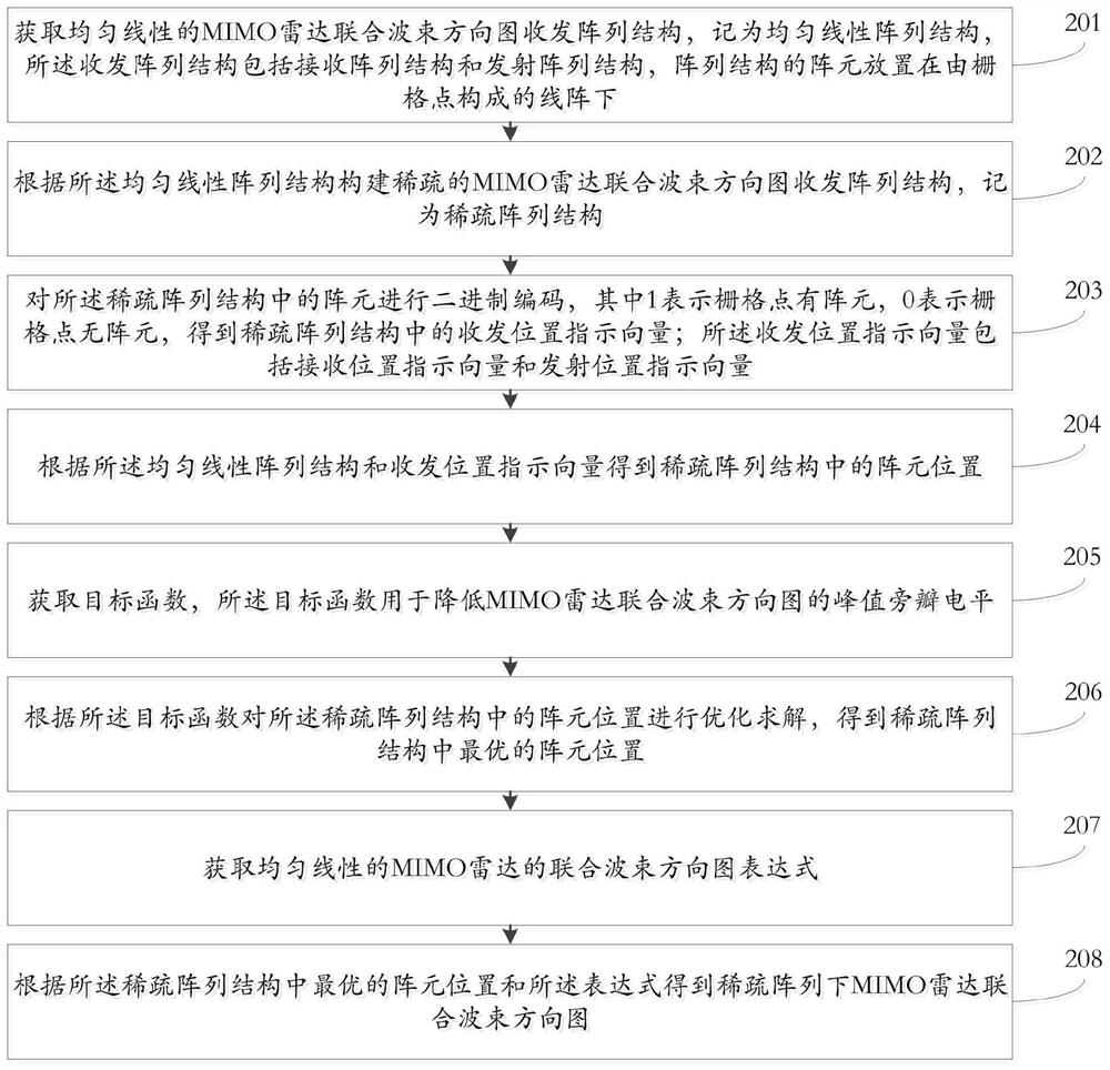
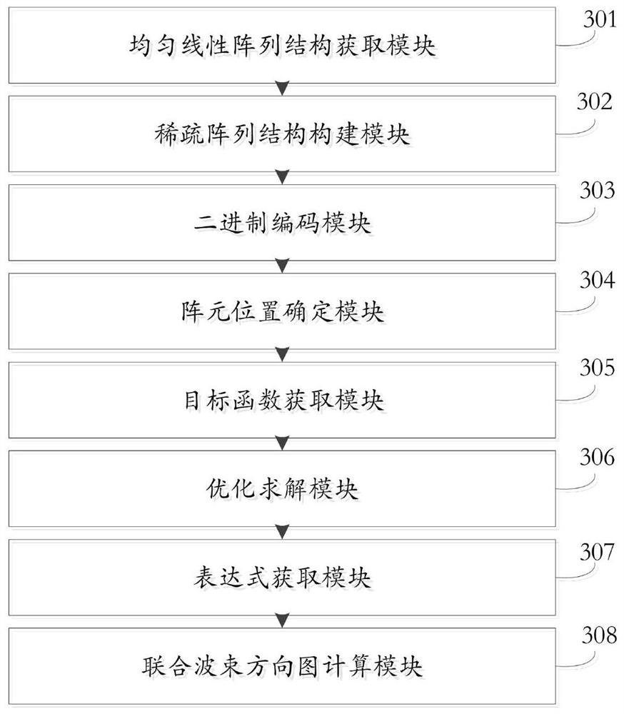
[0047] The following will clearly and completely describe the technical solutions in the embodiments of the present invention with reference to the accompanying drawings in the embodiments of the present invention. Obviously, the described embodiments are only some, not all, embodiments of the present invention. Based on the embodiments of the present invention, all other embodiments obtained by persons of ordinary skill in the art without making creative efforts belong to the protection scope of the present invention.

[0048] It should be noted that the terms "first" and "second" in the description and claims of the present invention and the above drawings are used to distinguish similar objects, but not necessarily used to describe a specific sequence or sequence. It is to be understood that the data so used are interchangeable under appropriate circumstances such that the embodiments of the invention described herein can be practiced in sequences other than those illustrate...


PUM


Abstract

The present invention relates to a method and system for synthesizing a sparse array MIMO radar joint beam pattern, the method comprising: obtaining a uniform linear MIMO radar joint beam pattern structure; constructing a sparse MIMO radar joint beam direction according to the uniform linear array structure The structure of the transceiver array is shown in the figure; the array elements in the sparse array structure are binary coded to obtain the transceiver position indicator vector in the sparse array structure; the array element position in the sparse array structure is obtained according to the uniform linear array structure and the transceiver position indicator vector; according to the acquisition The objective function of the sparse array structure is optimized to solve the array element position, and the optimal array element position in the sparse array structure is obtained; according to the optimal array element position in the sparse array structure and the joint beam of the obtained uniform linear MIMO radar The pattern expression obtains the joint beam pattern of MIMO radar under sparse array. The invention can improve the performance of radar target detection and parameter estimation.

Description

technical field [0001] The invention relates to the field of radar array signal processing, in particular to a method and system for synthesizing a sparse array MIMO radar joint beam pattern. Background technique [0002] Multiple input multiple output (MIMO) radar uses multiple transmitting antennas to transmit different orthogonal signals, and uses multiple receiving antennas to receive target echo signals, which can form a virtual array with a larger aperture. Control radar has obvious advantages and has become a popular new radar mode. Non-uniform arrays can achieve better performance with fewer array elements. The number of array elements in the system directly affects the cost, complexity and processing speed of the system. Therefore, the combination of MIMO radar system and non-uniform array arrangement can achieve higher performance with fewer array elements, and it is of great significance to study it in depth. [0003] In practical engineering applications, how ...

Claims


Application Information

Patent Timeline
Patent Type & Authority Patents(China)
IPC IPC(8): G01S7/02G01S7/42G01S13/89G01S13/90
CPCG01S7/02G01S7/42G01S13/89G01S13/90
Inventor 孙璐郝洁陈兵邓海
Owner NANJING UNIV OF AERONAUTICS & ASTRONAUTICS
Why Eureka
Try Eureka