Method for manufacturing a mould element for a tyre mould

A technology for tire molds and molds, which can be applied to household appliances, other household appliances, tires, etc., and can solve problems such as aluminum patterns are not resistant to tire curing environments or mold cleaning operations

Active Publication Date: 2021-08-06
MICHELIN & CO CIE GEN DES ESTAB MICHELIN
View PDF10 Cites 0 Cited by
  • Summary
  • Abstract
  • Description
  • Claims
  • Application Information

AI Technical Summary

Problems solved by technology

[0008] Moreover, regardless of the type of mold used for its manufacture, it is not possible to prepare patterns of small size on aluminum inserts (designed, for example, to obtain specific marks on molded tires), since such aluminum patterns are not resistant to Tire curing environment or mold cleaning operations

Method used


Image

  • Method for manufacturing a mould element for a tyre mould
  • Method for manufacturing a mould element for a tyre mould
  • Method for manufacturing a mould element for a tyre mould

Examples


Embodiment Construction

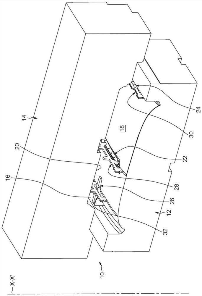
[0056] figure 1 Partly shown is an exemplary embodiment of a manufacturing apparatus, indicated generally at 10 , which is arranged for molding mold elements intended for tire curing moulds.

[0057] In the exemplary embodiment shown, the apparatus 10 is designed to be able to obtain, by moulding, mold elements which, when mounted in the associated curing molds, then allow the formation of a profile in the tread of the tyre. This is called an insert element.

[0058] Apparatus 10 includes a die 12 and an opposing die 14 each secured to two locations of the tool (not shown) and capable of being displaced along an axis of displacement between an open distanced position and a closed molding position. XX' move relative to each other. In the closed position of the device 10, the mold 12 and the opposing mold 14 bear against each other and define between them a molding cavity 16 of the mold element.

[0059] The molding cavity 16 defines in a concave manner the general shape of t...


PUM


Abstract

The method for manufacturing a mould element using a manufacturing device of the type comprising a die and a counter-mould defining a moulding cavity in the closed position, comprises the following steps: - opening the manufacturing device; - placing at least one insert (22), produced by laser sintering, against a moulding surface of the die; - mounting at least one wedge (28) on the die in abutment against said insert in order to immobilise it relative to said moulding surface; - closing the manufacturing device, the counter-mould pressing onto said wedge in order to keep said insert pressed against said moulding surface; - injecting aluminium into the moulding cavity of the manufacturing device; - opening the manufacturing device; - extracting from the manufacturing device the mould element provided with a moulding face at least formed by part of said insert and by the aluminium.

Description

technical field [0001] The present invention relates to the general field of molds for curing or vulcanizing vehicle tyres. [0002] More specifically, the invention relates to mold elements intended for such molds. Background technique [0003] Typically, a curing mold includes two lateral shells, each of which molds a sidewall of a tire, and a plurality of sectors for molding the tread of said tire. The casing and the sectors delimit an internal space intended to come into contact with the green tire green. [0004] To mold the tread of a tyre, the mold sectors comprise insert elements usually made of aluminium. An "insert element" is a part of a mold comprising a molding surface for molding at least a part of the rolling surface of a tread and the profile of said tread. [0005] To prepare these inserts, one solution is to use a mold of friable material, such as plaster, combined with aluminum fins intended to form the profile of the tire tread. The fins are placed in...

Claims


Application Information

Patent Timeline
Patent Type & Authority Applications(China)
IPC IPC(8): B29D30/06B29C33/30
CPCB29D30/0606B29D2030/0612B29D30/0662B29C33/306B33Y80/00B22D17/24B22D19/00B29C33/3842
Inventor D·唐吉J·莱普雷特雷
Owner MICHELIN & CO CIE GEN DES ESTAB MICHELIN
Why Eureka
Try Eureka