
Bending machine for forming corrugations in sheet metal and method of use

A technology for bending machines and metal plates, which is applied in the field of bending machines and can solve the problems of increasing the overall size of the bending machines.

Active Publication Date: 2021-08-03
GAZTRANSPORT & TECHNIGAZ SA
View PDF5 Cites 0 Cited by
  • Summary
  • Abstract
  • Description
  • Claims
  • Application Information

AI Technical Summary

Problems solved by technology

Moreover, the cam surface and the cam follower are arranged at the height of the sides of the upper frame and the mold element respectively, this auxiliary device leads to a significant increase in the overall size of the bending machine

Method used


Image

  • Bending machine for forming corrugations in sheet metal and method of use
  • Bending machine for forming corrugations in sheet metal and method of use
  • Bending machine for forming corrugations in sheet metal and method of use

Examples


Embodiment Construction

[0093] Figure 9 Shown is a corrugated metal sheet 1 for forming a fluid tight membrane for a storage tank for a cryogenic fluid such as liquefied natural gas.

[0094] Said rectangular metal plate 1 comprises a first series of parallel, so-called low corrugations 2, extending in the y-direction from one edge of the plate to the other, and a second series of parallel, so-called high corrugations 3, of high The corrugations 3 extend from one edge of the metal plate 1 to the other in the x-direction. The directions x and y of the series of ripples are perpendicular. The corrugations 2, 3 protrude, for example, from the inner surface side of the metal plate 1 to come into contact with the fluid contained in the tank. Here, the sides of the metal plate 1 are parallel to the corrugations 2,3. It is worth noting that the terms "high" and "low" have relative meanings and mean that the height of the so-called low corrugations 2 is lower than the height of the so-called high corruga...


PUM

PropertyMeasurementUnit
widthaaaaaaaaaa
lengthaaaaaaaaaa

Abstract

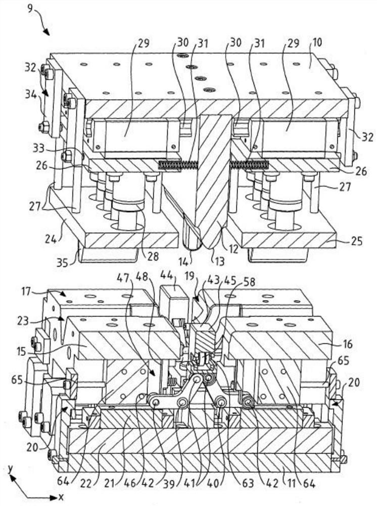
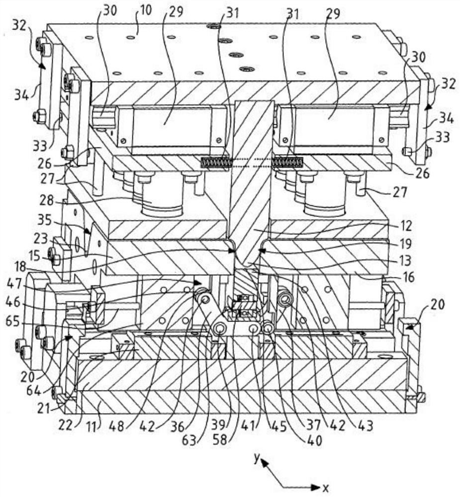
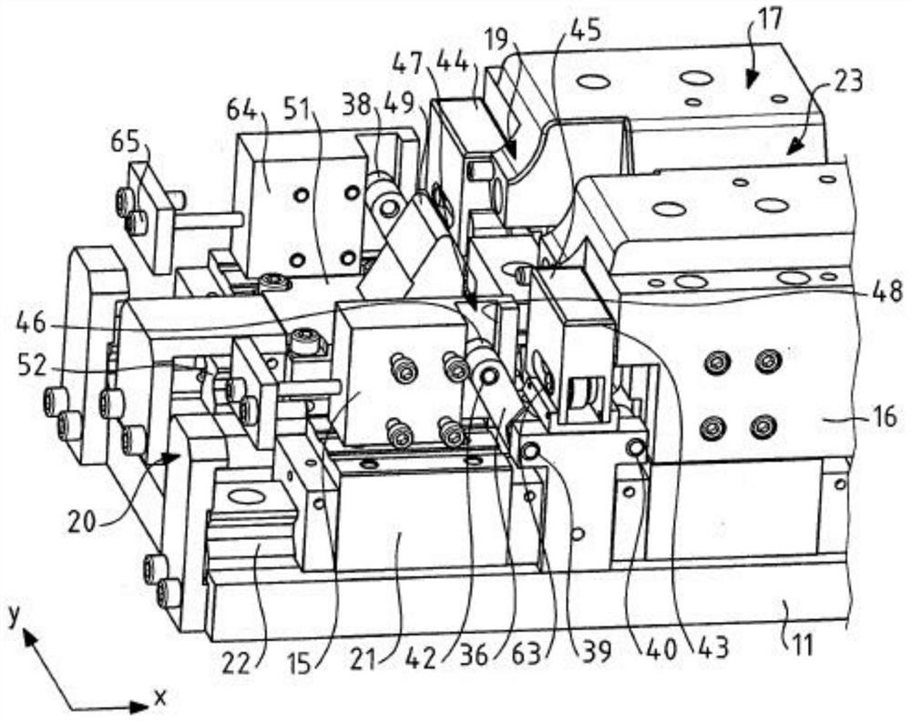
The invention relates to a bending machine (9) for forming corrugations (2) in a metal sheet (1) for the construction of fluid-tight membranes for fluid storage tanks, said bending machine (9) comprising:- frame (11); - a lower mold comprising first and second mold elements (15, 16) mounted on said lower frame (11) to slide in the x-direction; - an upper punch (12); - first and second die pads (24, 25); - said bending machine (9) also includes auxiliary devices (36, 37), said auxiliary devices (36, 37) Adapted to assist movement of said first and second mold elements (15, 16) into an engaged position. The invention also discloses a method of using the machine.

Description

technical field [0001] The invention relates to a bending machine for forming corrugations in sheet metal. [0002] Metal sheets produced by means of such bending machines are used in particular for the construction of sealing membranes for fluid storage tanks. Moreover, the invention also relates to the field of fluid-tight and thermally insulated membrane tanks for storage and / or transportation of eg cryogenic fluids. Background technique [0003] Document WO2015170054 discloses a bending machine for forming in a sheet metal comprising preformed corrugations, the corrugations being perpendicular to said preformed corrugations. The bending machine includes a lower die comprising a first die element and a second die element each having a sheet metal support surface and a concave half-dimple, the first die element and the second die element each mounted to Sliding on the lower frame in the x-direction, which is perpendicular to the direction of the corrugations to be formed...

Claims


Application Information

Patent Timeline
Patent Type & Authority Patents(China)
IPC IPC(8): B21D13/02F17C1/08
CPCB21D13/02B21D37/10F17C1/08
Inventor 奥利维尔·佩罗特安东尼·德法利亚托马斯·科内赫罗弗雷德里克·高斯里斯穆罕默德·萨西
Owner GAZTRANSPORT & TECHNIGAZ SA
Learn More