Safety device for punches in a compression moulding apparatus

A technology for safety devices and objects, applied in the direction of household components, applications, household appliances, etc., can solve problems such as damage to mold components or removal mechanisms, and achieve the effect of preventing damage

Active Publication Date: 2015-03-25
SACMI COOP MECCANICI IMOLA SOC COOP A R L
View PDF4 Cites 0 Cited by
  • Summary
  • Abstract
  • Description
  • Claims
  • Application Information

AI Technical Summary

Problems solved by technology

This failure to open means that by actuating the mechanism that removes the article from the punch, the removal ring itself will force itself against the die element, potentially damaging the die element or the removal mechanism

Method used


Image

  • Safety device for punches in a compression moulding apparatus
  • Safety device for punches in a compression moulding apparatus
  • Safety device for punches in a compression moulding apparatus

Examples


Embodiment Construction

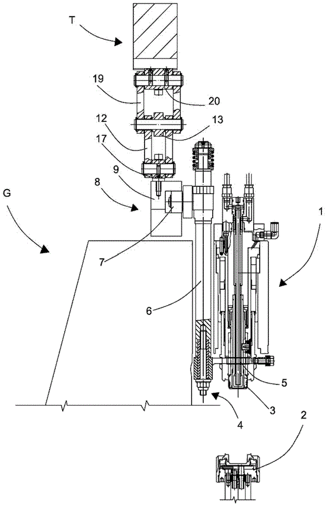
[0017] exist figure 1 In , the punches 1 and the corresponding mold elements of the conveyor belt G for molding caps are shown in the open position after molding an object 3 (such as a cap) and before the removal mechanism 4 removes the object 3 from the punch 1 2.

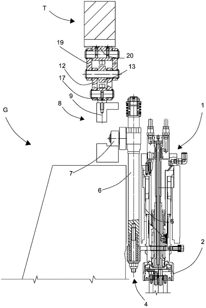
[0018] The molding conveyor belt G comprises a plurality of die elements 2 and a plurality of punches 1 arranged at a constant angular pitch along the periphery of the conveyor belt. The punch 1 is arranged in a fixed position, while the die element 2 can be figure 1 shown in the first lower position and figure 2 Vertical movement is shown between a second upper position, in which the die element 2 is clear of the punch 1 , and in a second upper position, in which the die element 2 interacts with the punch to mold the object 3 .

[0019] After the object 3 has been molded, the mold element 2 is lowered again to the first lower position, detached from the punch 1 , while the manufactured object 3 is still adher...


PUM


Abstract

A safety device for an apparatus for compression-moulding objects that includes a moulding carousel provided with a plurality of punches and with a plurality of corresponding moulding elements, each mould element being movable between a first position in which it does not interact with the respective punch and a second position in which it interacts with the respective punch to mould an object. Each punch is associated with an extracting device suitable for extracting from the respective punch a moulded object. The extracting device is driven by a cam track obtained in a fixed frame of the moulding carousel. The cam track includes a cam track portion that is movable between an operating position in which it interacts with the extracting device and a non-operating position in which it does not interact with the extracting device.

Description

technical field [0001] The present invention relates to a safety device for a punch of a device for forming an article, such as a compression molded cap. Background technique [0002] An apparatus for compression molding articles generally includes a molding conveyor belt provided with a plurality of mold elements each provided with a cavity for receiving a plastic compound to form an article. Each mold element is associated with a punch which, through interaction with the corresponding mold element, performs compression molding of the object. [0003] During the step of performing the molding of the object, the mold element is moved vertically upwards until the punch penetrates the cavity of the mold element in which the plastic compound has been placed and compresses said plastic compound in said cavity, forming the object. [0004] After the forming step has been completed, the mold element is lowered, returning the mold element to its original position, and the formed o...

Claims


Application Information

Patent Timeline
Patent Type & Authority Patents(China)
IPC IPC(8): B29C43/50B29C43/58B29C43/08
CPCB29C2037/94B29L2031/565B29C43/08B29C43/58B29C43/42B29L2001/00B29C2043/5866B29C43/50B29C2043/3288
Inventor G·阿尔迪赫里
Owner SACMI COOP MECCANICI IMOLA SOC COOP A R L
Why Eureka
Try Eureka