Connector

A technology of connectors and terminals, applied in the direction of connection, parts of connecting devices, devices to prevent wrong connections, etc.

Active Publication Date: 2021-08-06
AUTONETWORKS TECH LTD +2
View PDF13 Cites 0 Cited by
  • Summary
  • Abstract
  • Description
  • Claims
  • Application Information

AI Technical Summary

Problems solved by technology

If the tip of the protruding piece protrudes from the box and touches the detection piece, there is a problem that the detection function of the detection piece cannot be properly performed.

Method used


Image

  • Connector
  • Connector
  • Connector

Examples


Embodiment 1

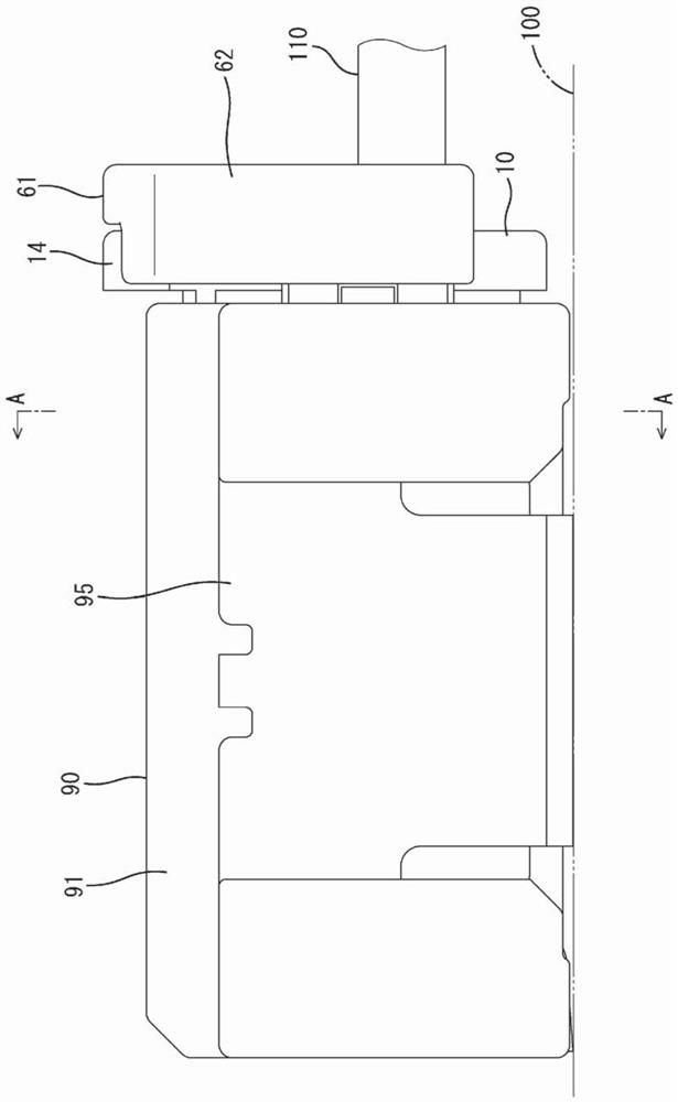
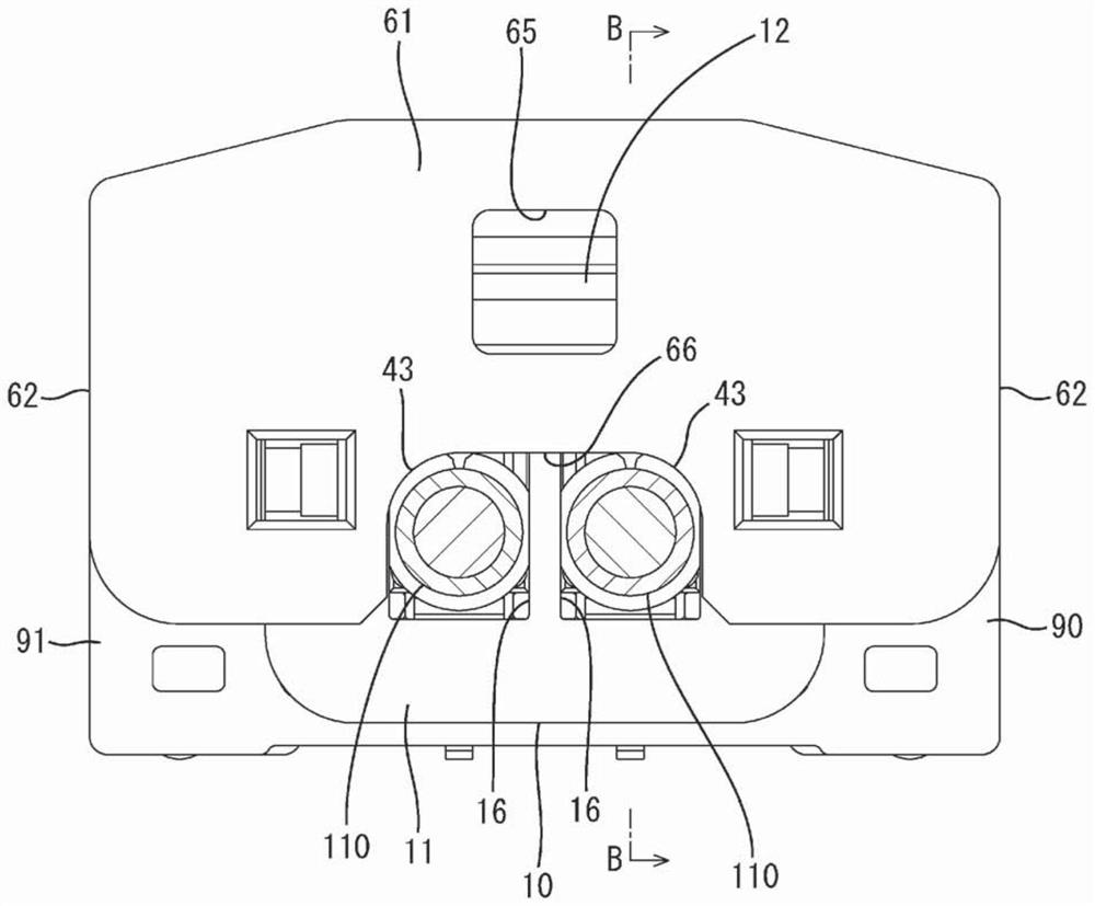
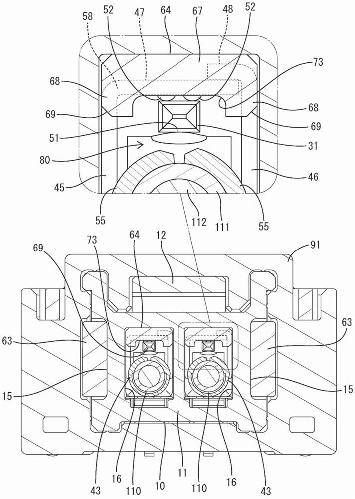
[0029] use Figure 1 to Figure 9 Example 1 of the present disclosure will be described. The connector of the first embodiment includes a housing 10 , a terminal component 40 housed in the housing 10 , and a stopper 60 attached to the housing 10 . The case 10 can be fitted with the mating case 90 . In addition, in the following description, regarding the front-rear direction, the surface side where both housings 10 and 90 face each other at the start of fitting is defined as the front side. Divide up and down Figure 8 and Figure 9 The vertical direction of each figure other than 1 is a reference.

[0030]

[0031] The counterpart housing 90 is made of synthetic resin and has a square tube-shaped cover portion 91, such as figure 1 As shown, it is mounted on the upper surface of the circuit board 100 . On the left and right sides of the cover portion 91, a pair of left and right fixing members 95 (in figure 1 only one is shown). The fixing member 95 is a metal plate, ...


PUM


Abstract

Provided is a connector making it possible for the function of a detection piece to be properly delivered. The connector is provided with: a housing (10) having a cavity (16); a terminal metal fitting (40) having a cylindrical box portion (41) which is inserted into the cavity (16) from the rear and the front and rear surfaces of which are open, wherein the tab (31) of a mating terminal metal fitting (30) is inserted into the box portion (41) from the front; and a retainer (60) having a detection piece (64) mounted on the housing (10) and capable of touching the rear end of the box portion (41). The detection piece (64) is provided with a recess portion (73) for avoiding the interference with the tab (31) passing through the box portion (41).

Description

technical field [0001] This disclosure relates to connectors. Background technique [0002] The connector disclosed in Patent Document 1 includes: a housing having a cavity; a terminal component inserted into the cavity from behind and having a cylindrical fitting portion (hereinafter referred to as a box portion) at the front end; and a stopper attached to the housing. The body has a flex locking piece (hereinafter referred to as a detection piece). Insert the tabs to connect the other terminal parts into the box. The detection piece comes into contact with the rear end of the box portion, restricts the terminal parts from coming out of the cavity, and detects the insertion state of the terminal parts. [0003] prior art literature [0004] patent documents [0005] Patent Document 1: Japanese Patent Laid-Open No. 2002-15807 Contents of the invention [0006] The problem to be solved by the invention [0007] In recent years, the connector tends to be reduced in siz...

Claims


Application Information

Patent Timeline
Patent Type & Authority Applications(China)
IPC IPC(8): H01R13/42H01R13/64
CPCH01R13/4367H01R13/432H01R13/11H01R13/46H01R13/642
Inventor 宫村哲矢牧野健司铃木晶子
Owner AUTONETWORKS TECH LTD
Why Eureka
Try Eureka