A sncr denitrification system applied to small boilers
A small boiler and boiler technology, applied in the field of SNCR denitrification system, can solve the problems of reducing agent reaction and denitrification efficiency reduction, and achieve the effect of improving denitrification efficiency
- Summary
- Abstract
- Description
- Claims
- Application Information
AI Technical Summary
Problems solved by technology
Method used
Image
Examples
Embodiment 1
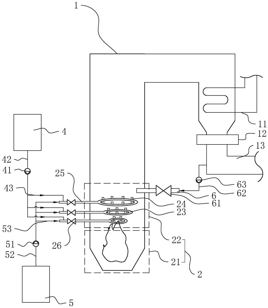
[0038] Embodiment one, refer to figure 1 , is an SNCR denitrification system applied to small boilers disclosed in the present invention, including a boiler 1, and an open flame area 2 is arranged in the boiler 1, and the open flame area 2 is a place where an open flame can be seen in the boiler 1, and the open flame area 2 is along the flue gas flow direction It includes an open flame front section 21 and an open flame tail section 22 in sequence.
[0039] Wherein, the suitable temperature for denitrification of the reducing agent in the boiler 1 is between 850-1100°C. During the load change of the small boiler 1, because the flue gas flows along the boiler 1, its temperature will continue to decrease, and the rate of decrease will first increase and then decrease, that is to say, the area with the smallest and most constant temperature change At the beginning of the flue gas (that is, the open flame area 2) and the tail section of the boiler 1. However, the temperature of ...
Embodiment 2
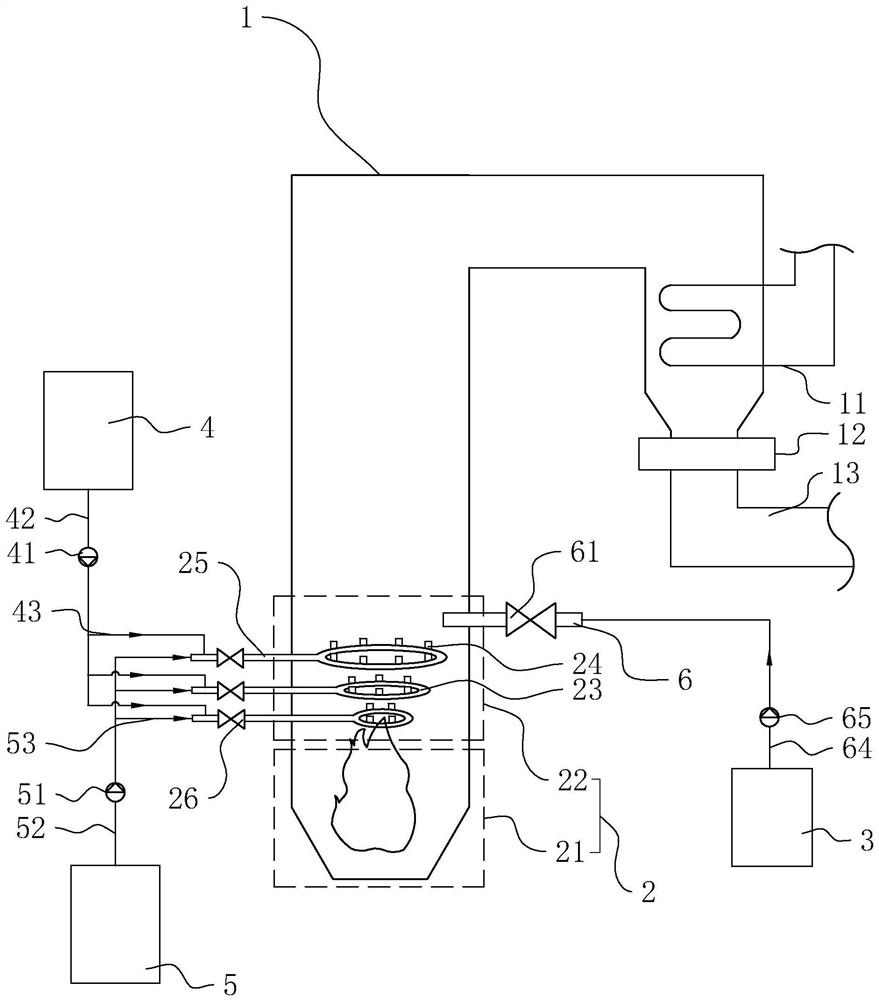
[0050] Embodiment two, refer to figure 2 , The only difference with Embodiment 1 is that there is no return air pipe 62 and circulating air pump 63, and a water tank 3, a water delivery pipe 64, and a water delivery pump 65 are provided.
[0051] The water tank 3 is arranged outside the boiler 1 , the water delivery pipe 64 communicates with the cooling spray gun 6 and is located between the outer end of the boiler 1 and the water tank 3 , and the water delivery pump 65 is installed on the water delivery pipe 64 .
[0052] The implementation principle of this embodiment is: by spraying urea into the tail section 22 of the open flame to improve the denitrification efficiency; at the same time, through the following two methods, the temperature after the urea temperature rises and decomposes is as close as possible to the suitable temperature range of the denitrification reaction, thereby improving denitrification efficiency. First, several ring pipes 23 at different ambient t...
Embodiment 3
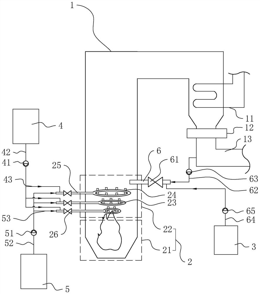
[0053] Embodiment three, refer to image 3 , The only difference with Embodiment 1 is that a water tank 3, a water delivery pipe 64, and a water delivery pump 65 are added.
[0054] The water tank 3 is located outside the boiler 1 , the water delivery pipe 64 communicates with the cooling spray gun 6 and is located between the outer end of the boiler 1 and the water tank 3 , and the water delivery pump 65 is installed on the water delivery pipe 64 .
[0055] The implementation principle of this embodiment is: by spraying urea into the tail section 22 of the open flame to improve the denitrification efficiency; at the same time, through the following two methods, the temperature after the urea temperature rises and decomposes is as close as possible to the suitable temperature range of the denitrification reaction, thereby improving denitrification efficiency. First, a plurality of ring pipes 23 at different ambient temperatures are provided, and appropriate ring pipes 23 are ...
PUM
 Abstract
Description
Claims
Application Information
 - R&D
- Intellectual Property
- Life Sciences
- Materials
- Tech Scout
- Unparalleled Data Quality
- Higher Quality Content
- 60% Fewer Hallucinations
Browse by: Latest US Patents, China's latest patents, Technical Efficacy Thesaurus, Application Domain, Technology Topic, Popular Technical Reports.
© 2025 PatSnap. All rights reserved.Legal|Privacy policy|Modern Slavery Act Transparency Statement|Sitemap|About US| Contact US: help@patsnap.com


