Aircraft with aircraft cooling system

A technology of cooling system and aircraft, applied in the cooling system of power plant, aircraft parts, aircraft control and other directions, to achieve the effect of excellent cooling capacity and large heat exchange area

Active Publication Date: 2013-06-12
AIRBUS OPERATIONS GMBH
View PDF5 Cites 0 Cited by
  • Summary
  • Abstract
  • Description
  • Claims
  • Application Information

AI Technical Summary

Problems solved by technology

However, fuel cells with high capacity to generate electricity also generate a lot of heat and therefore have high cooling requirements

Method used


Image

  • Aircraft with aircraft cooling system
  • Aircraft with aircraft cooling system
  • Aircraft with aircraft cooling system

Examples


Embodiment Construction

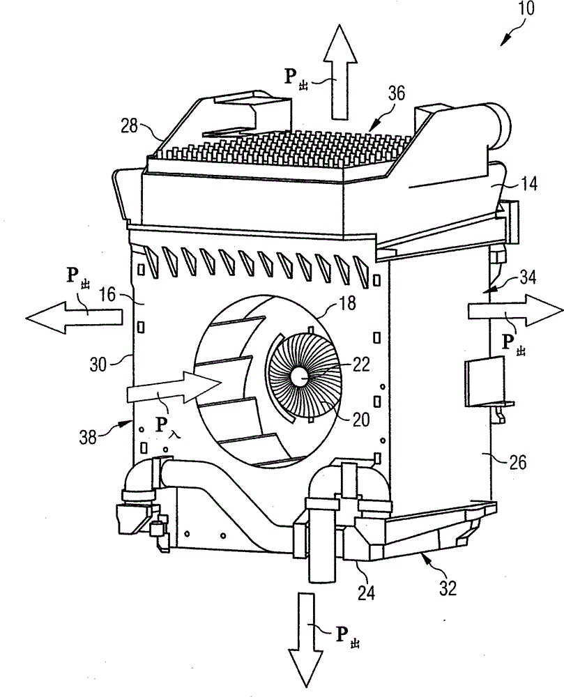
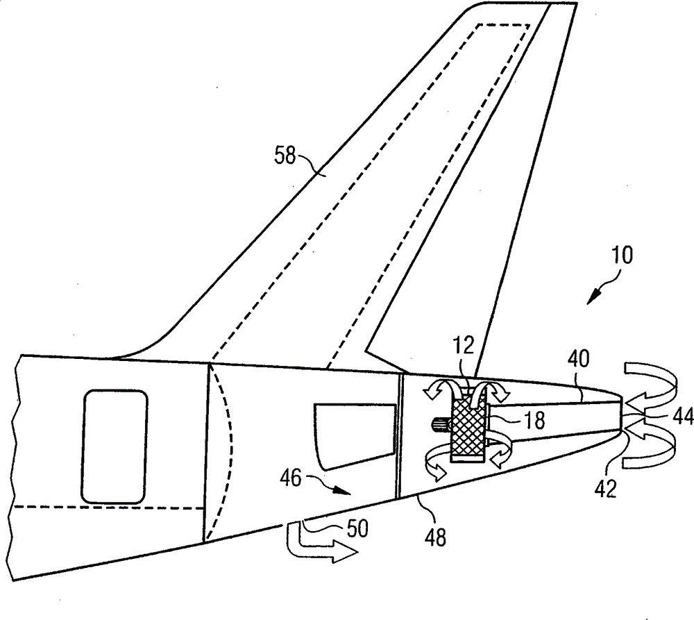
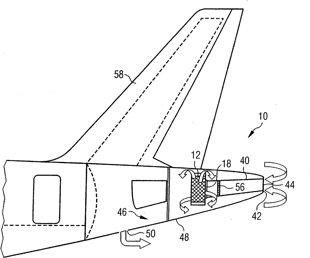
[0032] figure 1 shown suitable for use in Figure 2 to Figure 5 A cooling element 12 in an aircraft cooling system 10 is shown. The cooling element 12 includes a substantially cuboidal housing 14 . Cooling air inlets 18 are provided on the front side surface 16 of the cooling element 12 . A radial fan 20 is arranged in the region of the cooling air inlet 18 . A radial fan 20 is used in the direction of the cooling air inlet 18 (e.g. figure 1 Indicated by the arrow P in) sucking cooling air, and then radially outward with respect to the rotation axis 22 of the radial flow fan 20 (as figure 1 Shown by the arrow P in) to push the cooling air. On the side surfaces 24 , 26 , 28 , 30 of the cooling element 12 adjoining the front side surface 16 are provided heat exchangers 32 , 34 , 36 , 38 respectively. Cooling air flowing into the housing 14 of the cooling element 12 through the cooling air inlet 18 flows through the heat exchangers 32 , 34 , 36 , 38 and thereby transfers...


PUM


Abstract

An aircraft cooling system (10) comprises a cooling element (12), which comprises a housing (14), a cooling air inlet (18) formed in the housing (14) and a plurality of heat exchangers (32, 34, 36, 38), which are disposed on lateral surfaces (24, 26, 28, 30) of the housing (14) and through which cooling air supplied through the cooling air inlet (18) may flow. A cooling air supply channel (40, 40′) connects a cooling air supply opening (44, 44′) formed in a tail section of an aircraft to the cooling air inlet (18) of the cooling element (12). A cooling air outlet channel (46) connects the heat exchangers (32, 34, 36, 38) of the cooling element (12) to a cooling air discharge opening (50).

Description

technical field [0001] The invention relates to an aircraft cooling system particularly suitable for cooling fuel cell systems installed on board aircraft. Background technique [0002] Fuel cell systems can generate electricity with low radiation and high efficiency. For this reason, efforts are currently being made to utilize fuel cell systems to generate electrical energy in various mobile applications such as, for example, automotive engineering and aeronautics. For example, it is conceivable to replace the electrical generators currently used to supply electrical power on board aircraft and driven by the main or auxiliary engines (APU) with fuel cell systems in aircraft. Furthermore, the fuel cell system can also be used to supply emergency power to the aircraft and replace the ram air turbine (RAT) that has been used as the emergency power system. [0003] In addition to electrical energy, the fuel cell also generates thermal energy during operation, which has to be...

Claims


Application Information

Patent Timeline
Patent Type & Authority Patents(China)
IPC IPC(8): B64D33/10B64C21/04B64D13/00
CPCB64C21/06Y02T50/166B64D13/00B64D33/08Y02T50/10Y02T50/50
Inventor 托尔文·鲍姆加特阿尔夫-亨宁·斯托尔特沃克·皮尊卡乌韦·沃尔拉布
Owner AIRBUS OPERATIONS GMBH
Why Eureka
Try Eureka