Muffler
A muffler and outer tube technology, which is applied in the direction of mufflers, instruments, sound-generating instruments, etc., can solve the problems of easy deformation of small holes, poor processability, etc., and achieve the improvement of degree of freedom, proper muffler effect, and reduction of outer diameter Effect
- Summary
- Abstract
- Description
- Claims
- Application Information
AI Technical Summary
Problems solved by technology
Method used
Image
Examples
no. 1 approach
[0038] [Structure of the exhaust system]
[0039] figure 1 The illustrated exhaust system 1 includes a catalytic converter 3, a secondary muffler 5, a main muffler 7, and pipes 9A, 9B, and 9C (hereinafter collectively referred to as pipes 9 when no distinction is made between each pipe). It has a structure connected in series. The catalytic converter 3 is a device for purifying exhaust gas, and a catalyst is provided inside the catalytic converter 3 . Both the secondary muffler 5 and the main muffler 7 are devices for reducing exhaust noise. In the above structure, the sub muffler 5 corresponds to an example of the muffler of the present disclosure.
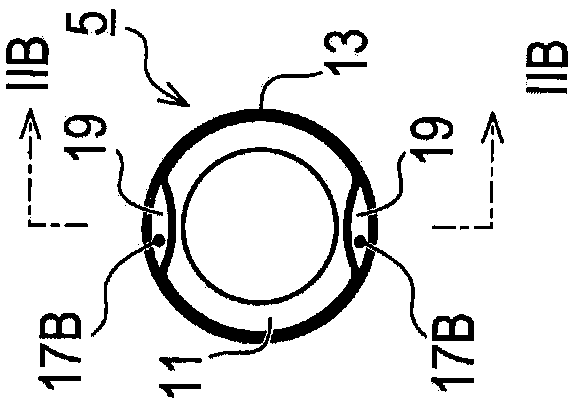
[0040] like Figure 2A as well as Figure 2B As shown, the secondary muffler 5 has an inner pipe 11 and an outer pipe 13 . Both the inner tube 11 and the outer tube 13 are formed in a tubular shape. The inner tube 11 is disposed on the inner peripheral side of the outer tube 13, whereby the inner tube 11 and the outer tub...
no. 2 approach
[0064] Next, a second embodiment will be described. In addition, each embodiment after the second embodiment will be described in detail focusing on the points of difference from the first embodiment. Only the same symbols as in the first embodiment are attached to the same parts as in the first embodiment in the drawings, and detailed description thereof will be omitted.
[0065] Figure 4A The exhaust system 31 shown has a catalytic converter 3, a first sub-muffler 5A, a second sub-muffler 5B, a main muffler 7, and pipes 9A, 9B, 9C, and 9D. structure. That is, the second embodiment differs from the first embodiment in that two sub-mufflers are provided.
[0066] According to the above structure, when air column resonance occurs in the exhaust pipe, even if the first sub-muffler 5A alone cannot cope with the air column resonance, by arranging the second sub-muffler 5B at the position caused by the air column resonance The sound pressure abdomen of the generated standing w...
no. 3 approach
[0068] Next, a third embodiment will be described.
[0069] Figure 4B The illustrated exhaust system 41 includes a catalytic converter 3 , a first sub-muffler 5A, a second sub-muffler 5B, a main muffler 7 , and pipes 9A, 9B, and 9C, and these components have a structure connected in series. The point that two sub-mufflers 5A, 5B are provided is the same as that of the second embodiment.
[0070] However, in the third embodiment, one end of the second sub-muffler 5B is directly connected to the main muffler 7 . In this way, the two ends of the sub-muffler 5 corresponding to the muffler of the present disclosure are not limited to connecting pipe materials, and may be directly connected to various devices that can constitute the exhaust flow path.
PUM
 Abstract
Description
Claims
Application Information
 - R&D
- Intellectual Property
- Life Sciences
- Materials
- Tech Scout
- Unparalleled Data Quality
- Higher Quality Content
- 60% Fewer Hallucinations
Browse by: Latest US Patents, China's latest patents, Technical Efficacy Thesaurus, Application Domain, Technology Topic, Popular Technical Reports.
© 2025 PatSnap. All rights reserved.Legal|Privacy policy|Modern Slavery Act Transparency Statement|Sitemap|About US| Contact US: help@patsnap.com


