Electric power steering device

a technology of electric power steering and steering wheel, which is applied in the direction of electric steering, power driven steering, vehicle components, etc., can solve the problems of large impact noise, damage or deformation of components, damage or deformation, and target current value, and achieve the effect of improving mountability on the vehicl

Inactive Publication Date: 2009-05-07
HONDA MOTOR CO LTD
View PDF12 Cites 41 Cited by
  • Summary
  • Abstract
  • Description
  • Claims
  • Application Information

AI Technical Summary

Benefits of technology

[0016]According to this structure, the rotation terminating mechanism can alter the allowable range of turning operation of the operator, by the deceleration mechanism. Therefore, the driver operating the steering wheel (operator) can be provided with the same range of steering angle (operation amount) including right and left as the range in the conventional device.
[0027]In this rotation terminating mechanism, the rotation of the thread portion is converted into the vertical shift of the second and third stoppers, and the rotation angle of the thread portion until the first projection of the first stopper is brought into contact with the second projection of the second stopper or the third projection of the third stopper becomes large. Therefore, the driver operating the steering wheel (operator) can be provided with the same range of steering angle (operation amount) including right and left as the range in the conventional device. In addition, in this rotation terminating mechanism, the steering angle including right and left of the steering wheel can be set to a value as large as, for example, 2 turns or more (i.e., 720° or more), and thus can be applied to vehicles other than automobile. At the same time, since the device does not have gears, the outer diameter of the rotation terminating mechanism can be made small, further improving mountability on the vehicle.

Problems solved by technology

In accordance with this larger steering torque, a larger auxiliary steering force is imparted from the electric motor to the steering unit, which may lead to a large impact on the rack end mechanism, or a large overload on rack-and-pinion gears, resulting in large impact noise, damage or deformation of components, or the like.
Furthermore, due to a rotational kinetic energy caused by inertia moment of the electric motor, overshoot of the electric motor rotation may occur, which may also lead to a large impact or large overload on components, such as rack gear, resulting in damage or deformation.
However, in the device of Japanese examined patent publication No. 6-4417, when the steering wheel is turned in an opposite direction at a position near the rack end angle, a target current value is limited until the turning angle becomes the predetermined angle or less, and thus a sufficient auxiliary steering force in accordance with the steering torque cannot be supplied to the steering unit.
As a result, the steering wheel becomes heavier, a practical rack end angle to which the driver can operate the steering wheel becomes smaller, and the steering wheel cannot be turned to the rack end angle which is mechanically set.
In addition, when an absolute value of a rotational speed ω of the motor is smaller than a set value |ω1|, or when the rack end is brought into contact at a high rotational speed ω of the motor, the rotation of the electric motor may undergo overshoot due to the kinetic energy by the inertia moment of the electric motor, and thus components, such as rack gear, may still suffer a large impact or overload.
Moreover, due to the overload on the motor, the motor may be burnt out.

Method used


Image

  • Electric power steering device
  • Electric power steering device
  • Electric power steering device

Examples


first embodiment

[0060]A first embodiment of the present invention will be described with reference to FIGS. 1 to 9A-9C.

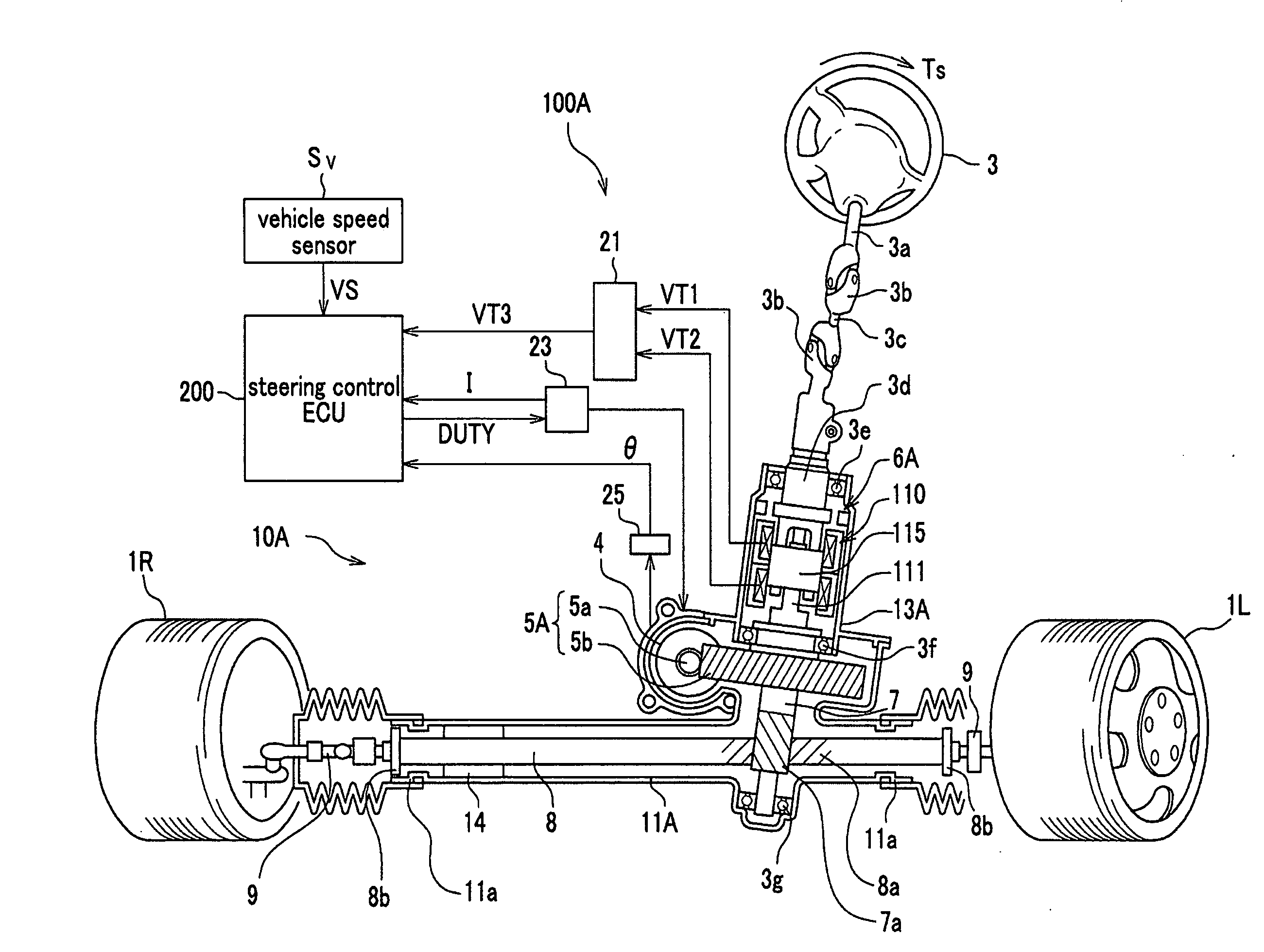
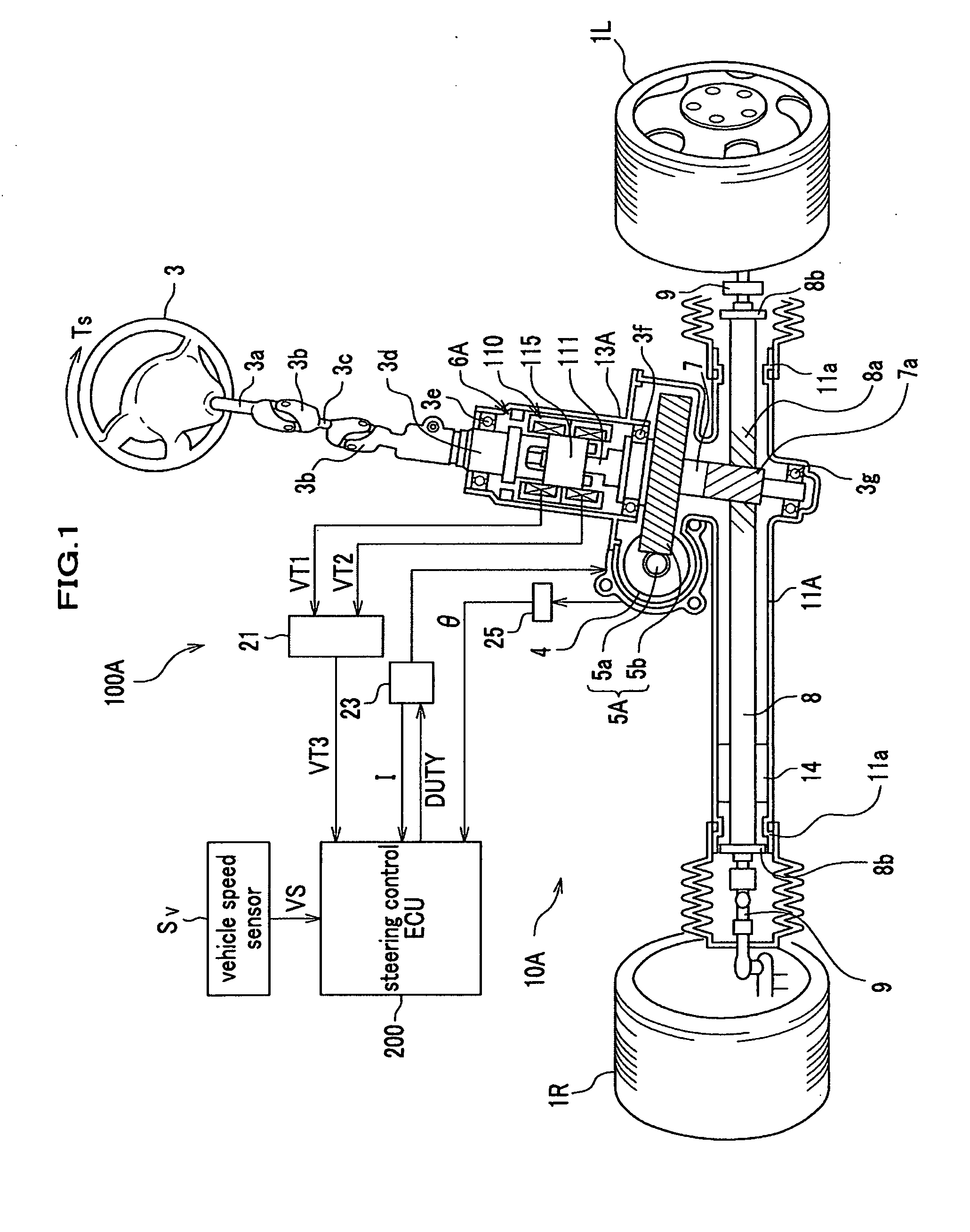
[0061]FIG. 1 is a configuration diagram of an electric power steering device according to the first embodiment of the present invention.

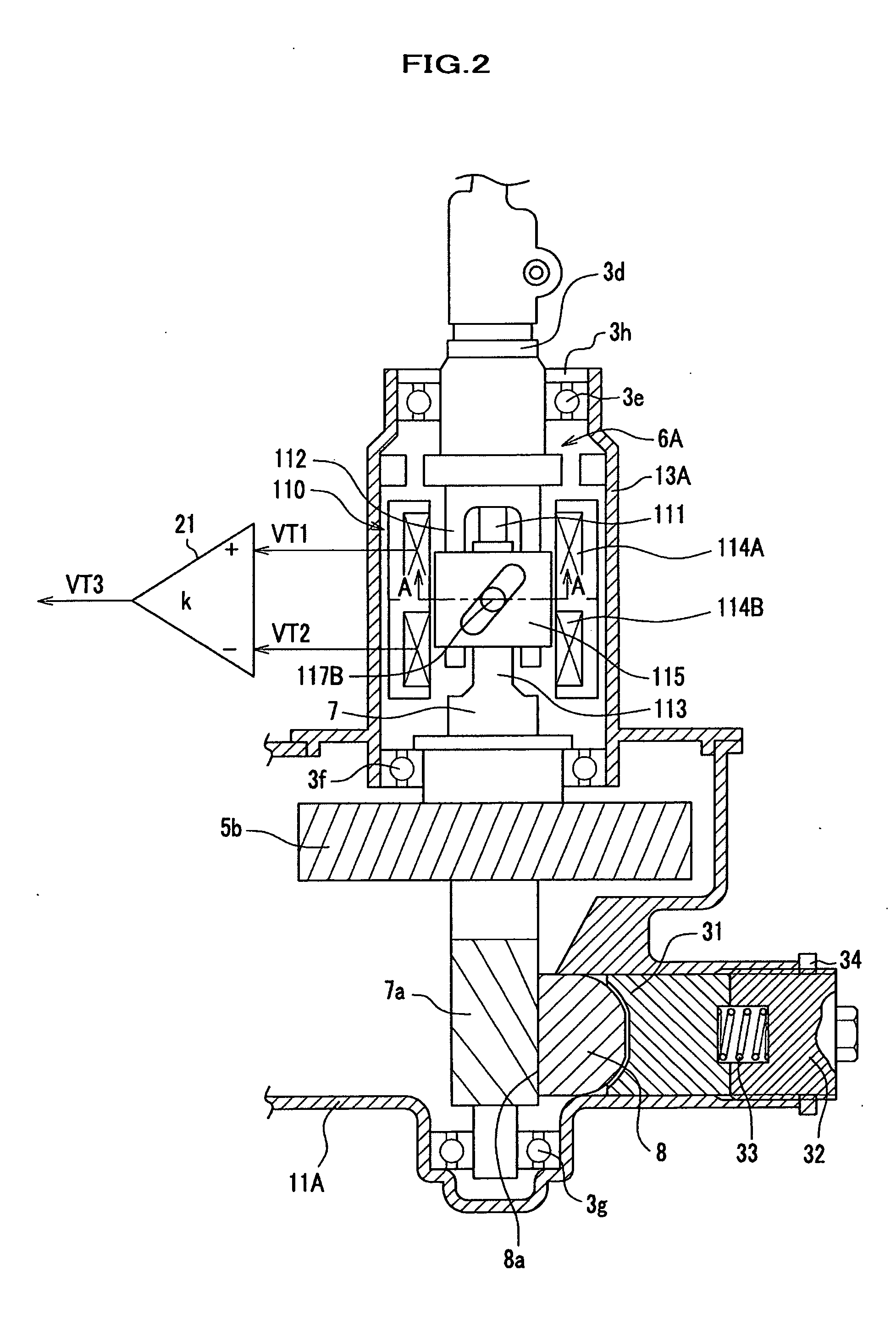
[0062]FIG. 2 is a side view showing portions around a torque sensor and a pinion gear in a steering gear box of FIG. 1.

[0063]An electric power steering device 100A includes, as shown in FIG. 1, a steering wheel (operator) 3, a steering wheel shaft 3a attached thereto, a shaft 3c and an input shaft 3d, all of which shafts are connected through two universal joints 3b. The input shaft 3d is connected to a pinion shaft 7 through a torsion bar 111. On a lower end of the pinion shaft 7, there is provided a pinion gear 7a, which is configured to engage with a rack gear 8a of a rack shaft 8 which can reciprocate in a vehicle width direction. To respective ends of the rack shaft 8, the left front wheel 1L and the right front wheel 1R are connected through ...

second embodiment

[0171]Next, with reference to FIG. 14, an electric power steering device according to the second embodiment of the present invention will be described.

[0172]FIG. 14 is a configuration diagram of an electric power steering device according to the second embodiment of the present invention. An electric power steering device 100B of the present embodiment is configured to perform assist driving of the rack shaft 8 by the electric motor 4, through a ball screw 5c.

[0173]The present embodiment is different from the first embodiment in that the electric motor 4 drives the deceleration mechanism (auxiliary torque transmission mechanism) 5B formed of the worm gear 5a and the worm wheel gear 5b, and the ball screw 5c, to thereby directly convert a rotational motion of the ball screw 5c to a linear motion of the rack shaft 8, unlike the first embodiment in which the electric motor 4 drives the pinion shaft 7 through the worm gear 5a and the worm wheel gear 5b.

[0174]In addition, the present e...

third embodiment

[0186]Next, with reference to FIG. 15, an electric power steering device according to a third embodiment of the present invention will be described.

[0187]FIG. 15 is a configuration diagram of an electric power steering device according to the third embodiment of the present invention. An electric power steering device 100C of the present embodiment is configured to perform assist driving of the steering wheel shaft 3a by the electric motor 4, through the worm gear 5a and worm wheel gear 5b.

[0188]The present embodiment is different from the first embodiment in that the electric motor 4 drives the steering wheel shaft 3a through the deceleration mechanism (auxiliary torque transmission mechanism) 5A formed of the worm gear 5a and the worm wheel gear 5b, unlike the first embodiment in which the electric motor 4 drives the pinion shaft 7 through the worm gear 5a and the worm wheel gear 5b.

[0189]In addition, the present embodiment is different from the first embodiment in that a torque...


PUM


Abstract

An electric power steering device is configured to transmit an auxiliary torque to a steering unit of front wheels, and includes: an operator; an electric motor configured to generate the auxiliary torque in accordance with at least a steering torque generated by input from the operator; the steering unit of front wheels which includes a pinion shaft; and a rotation terminating mechanism which provides a motion terminating end of the operator, the rotation terminating mechanism being disposed between the operator and the pinion shaft.

Description

CROSS-REFERENCE TO RELATED APPLICATIONS[0001]This application claims the foreign priority benefit under Title 35, United States Code, section 119 (a)-(d), of Japanese Patent Applications No. 2007-288070 filed on Nov. 6, 2007 and No. 2008-221214 filed on Aug. 29, 2008 in the Japan Patent Office, the disclosures of which are herein incorporated by reference in their entirety.BACKGROUND OF THE INVENTION[0002]1. Field of the Invention[0003]The present invention relates to an electric power steering device in which an auxiliary steering force is imparted from an electric motor to a steering unit of a vehicle such as an automobile.[0004]2. Description of the Related Art[0005]An electric power steering device is a device in which an electric motor generates an auxiliary torque in accordance with a magnitude of a steering torque, and the auxiliary torque is transmitted to a steering unit, to thereby reduce a steering effort required by a driver for steering.[0006]In a general electric power...

Claims


Application Information

Patent Timeline
Patent Type & Authority Applications(United States)
IPC IPC(8): B62D5/04
CPCB62D1/16B62D5/0469B62D5/04
Inventor SHIMIZU, YASUOWATANABE, KATSUJIYONEDA, ATSUHIKOYAMAWAKI, SHIGERU
Owner HONDA MOTOR CO LTD
Why Eureka
Try Eureka