Electric Pump

a technology of electric motors and motors, applied in the field of electric motors, can solve the problems of poor mountability and inability to reduce the axial length of the pump, and achieve the effect of improving mountability and reducing the size of the electric motor

Active Publication Date: 2008-01-24
HITACHI ASTEMO LTD
View PDF12 Cites 30 Cited by
  • Summary
  • Abstract
  • Description
  • Claims
  • Application Information

AI Technical Summary

Benefits of technology

[0011] The present invention makes it possible to reduce the size of an electric motor as a whole because of absence of coil ends, thus providing significantly improved mountability.

Problems solved by technology

This makes it impossible to reduce the axial length of the pump.
As a consequence, the pump is large as a whole, resulting in poor mountability.

Method used


Image

  • Electric Pump
  • Electric Pump
  • Electric Pump

Examples


first embodiment

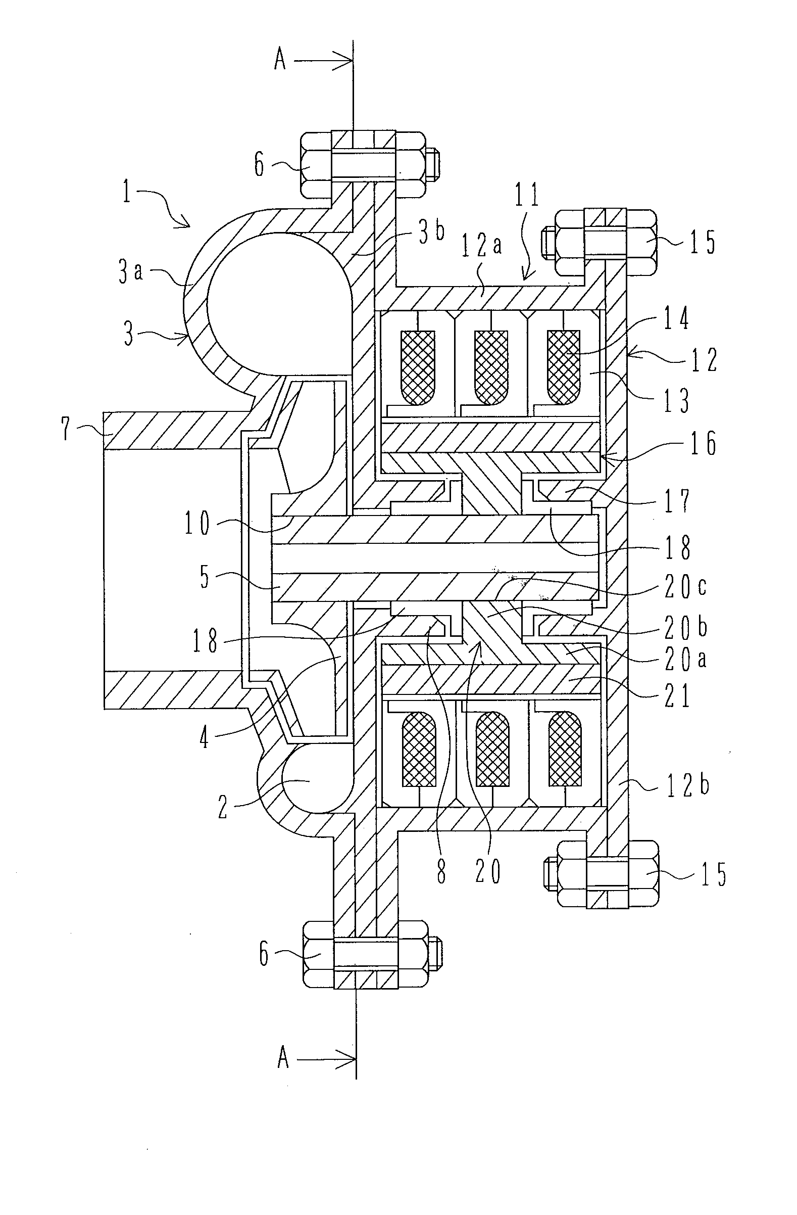
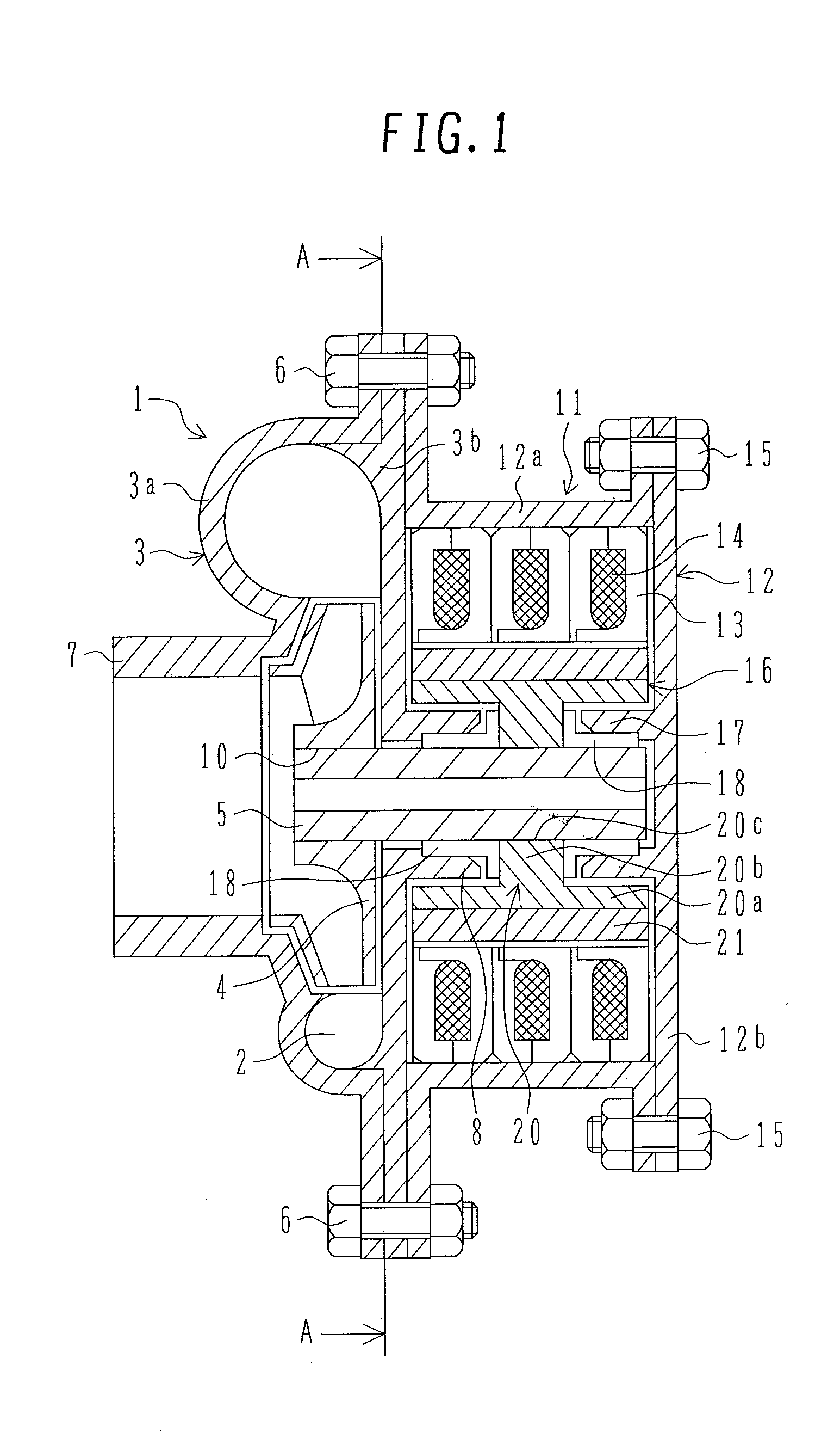
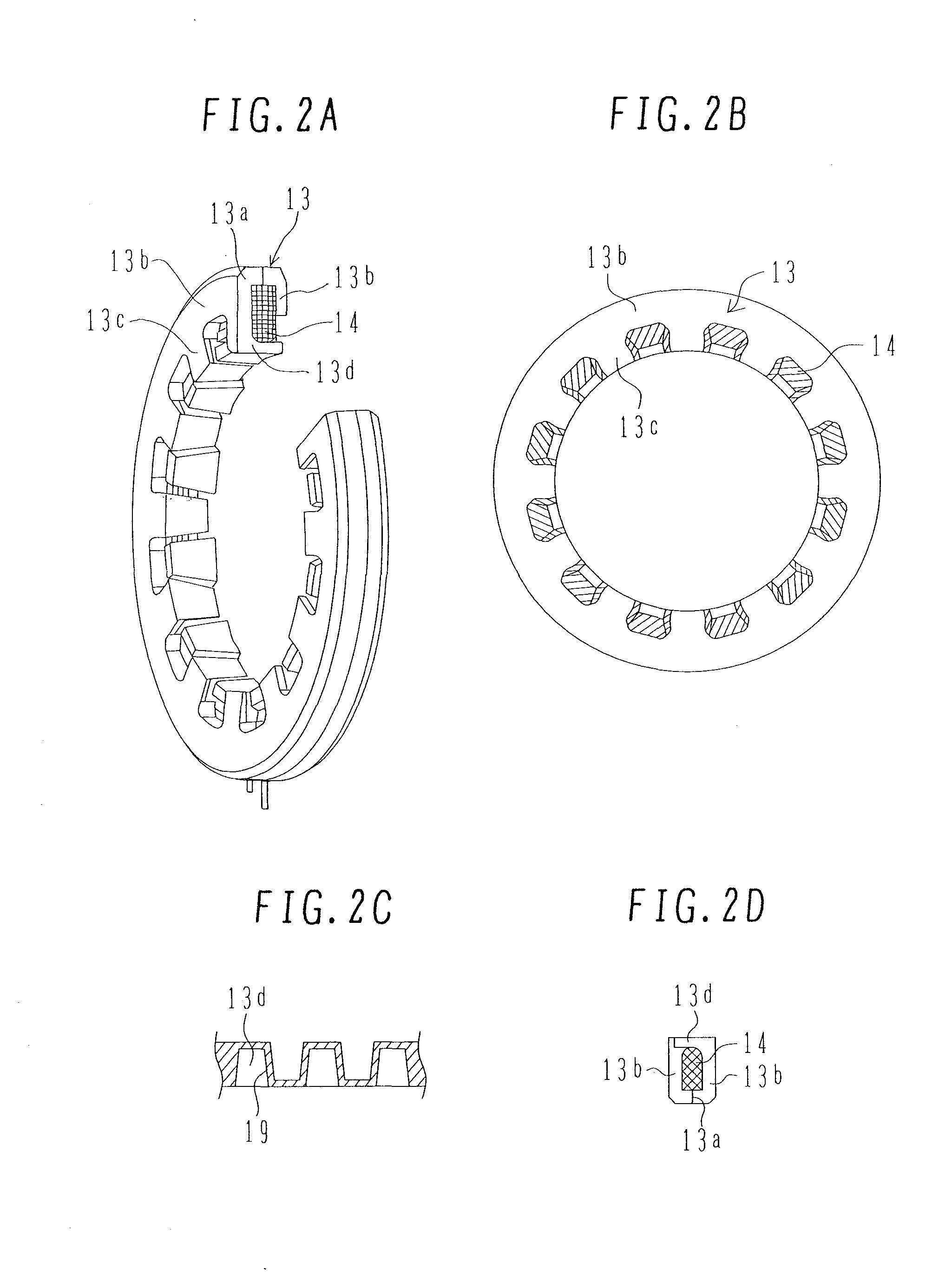
[0024] FIGS. 1 to 3 illustrate an electric motor of a first embodiment. FIG. 1 is a sectional view of the axial side surface of the electric water pump of the first embodiment. FIGS. 2A to 2D are views describing in detail a stator core for one phase and a coil of the first embodiment. FIG. 2A is a perspective view of the partial section of the stator core and the coil. FIG. 2B is a front view of the stator core. FIG. 2C is a developed view, in the circumferential direction, of the inner periphery of the stator core as seen from the inside. FIG. 2D is a sectional view of the partial side of the stator core and the coil. FIG. 3 is a sectional view along line A-A of FIG. 1.

[0025] The electric water pump is designed primarily for use in hybrid vehicles driven by an engine and a drive electric motor in combination so as to cool the drive electric motor or the starter-generator and its controller and other devices.

[0026] In FIG. 1, a water pump unit 1 as a pump structural body uses a c...

second embodiment

[0079]FIGS. 5A to 5C illustrate the electric water pump of a second embodiment. FIG. 5A is a sectional view of the axial side surface of the electric water pump as the second embodiment. FIG. 5B is a sectional view along line B-B of FIG. 5A. FIG. 5C is a side view of only the stator cores molded with a resin which is a non-magnetic material. It is to be noted that the same parts as those in the first embodiment are termed the same names and denoted by the same reference numerals.

[0080] The second embodiment differs from the first embodiment in that the molded portion 19 of the stator cores 13 molded with a resin, a non-magnetic material, is provided with channels 34 through which cooling water as a cooling medium can flow.

[0081] As shown in FIG. 5B, the channels 34 include channels 34a, 34b and 34c. The channel 34a is an annular channel provided in an annular shape at the approximate center of the circular portion in the direction of radius on the axial end surface of the stator c...

third embodiment

[0091]FIG. 6 and FIGS. 7A and 7B illustrate the electric water pump of a third embodiment. FIG. 6 is a sectional view of the axial side surface of the electric water pump of the third embodiment. FIGS. 7A and 7B are views describing in detail the stator core and coil of the third embodiment. FIG. 7A is a perspective view of the partial section of the stator core as a core and the coil of the third embodiment. FIG. 7B is a front view of the stator core. It is to be noted that the same parts as those in the first embodiment are termed the same names and denoted by the same reference numerals.

[0092] The third embodiment differs from the first embodiment in that a single-phase motor is used which includes the single-phase stator core 13. The third embodiment also differs in that a stepped portion 35 is provided on one circumferential side of each of the claw portions 13d of the claw magnetic poles. The third embodiment also differs in that a position detector 36 is provided to detect t...


PUM


Abstract

The present invention provides a compact electric motor, thus ensuring improved in-vehicle mountability. A pump is driven by an electric motor. The pump has a coil 14 disposed in a ring form around and along a stator core 13. The stator core 13 has a plurality of claw magnetic poles which extend alternately from both ends of one member of the stator core 13 toward the end of the other member thereof. The electric motor drives the pump by rotating a rotor 16 disposed to face the inner periphery of the stator core 13 as the coil 14 is energized. The present invention provides a compact electric pump with no coil ends, thus ensuring improved in-vehicle mountability. Further, the present invention permits efficient cooling of the electric motor adapted to discharge a cooling medium. Still further, the present invention permits the use of a stator core made from a compressed powder core by molding with resin. In addition, the molded portion also serves as a partition separating pump and motor units.

Description

BACKGROUND OF THE INVENTION [0001] 1. Field of the Invention [0002] The present invention relates to an electric pump driven by an electric motor. [0003] 2. Description of the Related Art [0004] Among measures to improve automobile fuel efficiency are firstly idling stop adapted to stop an engine when a vehicle stops, and secondly hybridization adapted to drive a vehicle using a rotary electric machine and an engine. These measures have already found commercial use. To use these systems, a drive source is additionally required for a pump in the case of an idling stop system because the engine stops when the vehicle stops. In the case of hybrid vehicles, on the other hand, a water pump is required to cool the drive motor or starter-generator and its controller in addition to the idling stop system. As a result, an electric pump using an electric motor is increasingly common as a drive source. [0005] JP-A-2000-213490 discloses an electric motor adapted to discharge cooling water by us...

Claims


Application Information

Patent Timeline
Patent Type & Authority Applications(United States)
IPC IPC(8): F04D13/06H02K1/00H02K3/00B60L50/16
CPCH02K1/02Y02T10/641H02K5/12H02K7/14H02K21/145F04D13/0633F04D13/064B60L1/003B60L1/02B60L3/0061B60L11/14B60L2210/40B60L2240/34B60L2240/36B60L2240/425B60L2270/142B60L2270/145Y02T10/7077Y02T10/7241Y02T10/642Y02T10/70H02K1/145B60L50/16F04D13/0653F05D2230/22F05D2260/36Y02T10/64Y02T10/7072Y02T10/72
Inventor TAJIMA, FUMIOKITAMURA, MASASHIENOMOTO, YUJINOMOTO, YUJITAKARAI, KENYA
Owner HITACHI ASTEMO LTD
Why Eureka
Try Eureka