Torque detecting apparatus and manufacturing method thereof

a technology of torque detection and manufacturing method, which is applied in the direction of instruments, instruments, and instruments for force/torque/work measurement, etc., can solve the problems of short circuit of magnetic circuit, large number of components, and large number of steps of installation operation, and achieve the effect of reducing the number of components

Inactive Publication Date: 2005-10-13
JTEKT CORP +1
View PDF26 Cites 30 Cited by
  • Summary
  • Abstract
  • Description
  • Claims
  • Application Information

AI Technical Summary

Benefits of technology

[0011] The present invention has been made with the aim of solving the above problems, and it is an object thereof to provide a torque detecting apparatus which can reduce the number of components and, further, can be incorporated from one direction.
[0012] Another object of the present invention is to provide a torque detecting apparatus which can reduce a short circuit of the magnetic circuit due to magnetic dust or a short circuit of the magnetic circuit due to run-out of the rotor.
[0013] Another object of the present invention is to provide a manufacturing method of a torque detecting apparatus which can reduce the number of components and enhance the installability into the housing.

Problems solved by technology

In a torque detecting apparatus constructed as disclosed in Japanese Patent Application Laid-Open No. 2003-149062, however, since the detecting unit and the detection circuit board are formed separately from each other and it is necessary to connect the detecting unit with the detection circuit board by a conductor, there are problems that the number of components is large and the number of steps of the installation operation is large.
Furthermore, since a permanent magnet is used, magnetic dust such as iron powder may enter the magnetic circuit causing a short circuit of the magnetic circuit and a deviation of a detection signal of the magnetism sensitive element, and a solution has been required.
Moreover, since a space exists between the permanent magnet provided on the input shaft and the rotary magnetic rings provided on the output shaft to allow relative rotation, the run-out of the input shaft and the output shaft may cause a contact between the permanent magnet and the rotary magnetic rings and a short circuit of the magnetic circuit, and a solution has been also required for this point.

Method used


Image

  • Torque detecting apparatus and manufacturing method thereof
  • Torque detecting apparatus and manufacturing method thereof
  • Torque detecting apparatus and manufacturing method thereof

Examples


embodiment 1

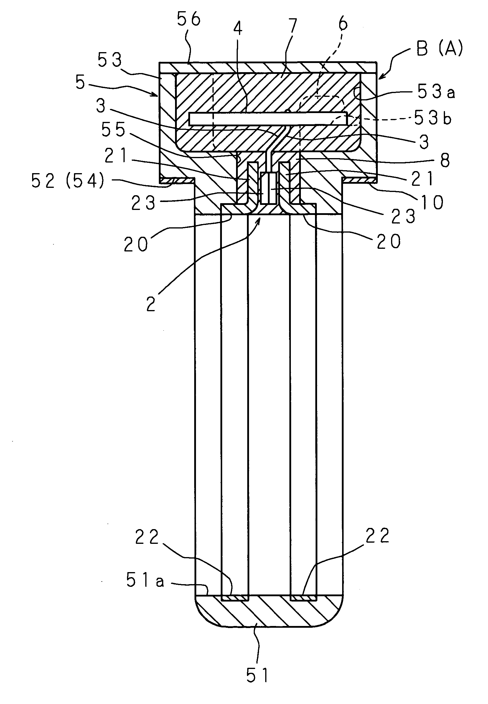
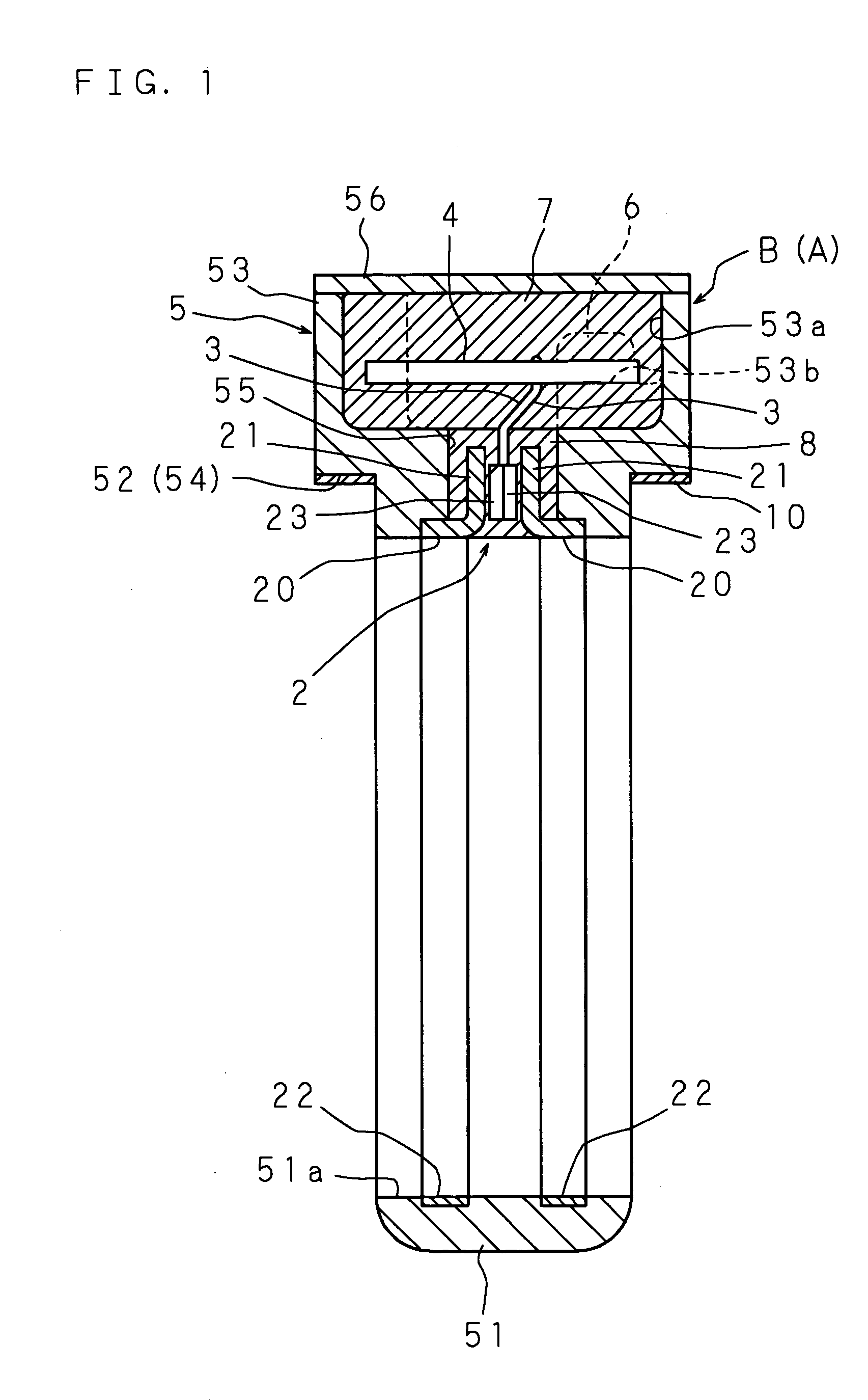
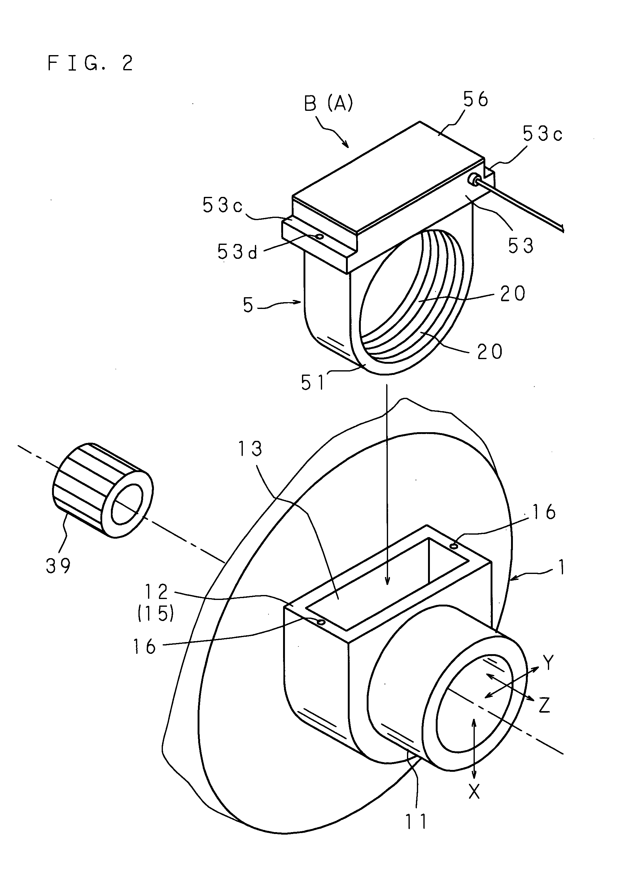
[0049]FIG. 1 is a sectional view showing the structure of a torque detecting apparatus according to Embodiment 1 of the present invention; FIG. 2 is an exploded perspective view of a mold member and a housing; FIG. 3 is a sectional view showing a portion in an enlarged manner; FIG. 4 is an explanatory view of installation of the mold member into the housing; FIG. 5 is a perspective view showing a portion in an exploded manner; and FIG. 6 is an explanatory view of a magnetic circuit which is generated when a rotor rotates in one direction.

[0050] A torque detecting apparatus A comprises: a cylindrical housing 1 surrounding a rotor which is composed of an input shaft and an output shaft connected coaxially with each other by a torsion bar and has a permanent magnet and a pair of rotary magnetic rings that can freely rotate relatively; a detecting unit 2 which is arranged around the periphery of the rotary magnetic rings provided on the rotor in the housing 1; and a detection circuit b...

embodiment 2

[0072]FIG. 10 is a vertical sectional view showing the structure of a torque detecting apparatus according to Embodiment 2 of the present invention; FIG. 11 is an enlarged sectional view of the torque detecting apparatus; FIG. 12 is an exploded perspective view of an essential portion; FIG. 13 is an explanatory view of a magnetic circuit which is generated when a rotor rotates in one direction; and FIGS. 14A, 14B and 14C are sectional views showing the structure of the essential portion in an exploded manner. The same codes are used to refer to the same components as Embodiment 1 and detailed explanation thereof is omitted.

[0073] A torque detecting apparatus A comprises: a permanent magnet 39 provided at a peripheral portion of a first rotor 33a; a pair of rotary magnetic rings 40 and 40 which are arranged around the periphery of the permanent magnet 39 and are provided at a second rotor 33b that is connected coaxially with the first rotor 33a by a torsion bar 31; two static magnet...


PUM

PropertyMeasurementUnit
torqueaaaaaaaaaa
magnetismaaaaaaaaaa
magnetism sensitiveaaaaaaaaaa

Abstract

A detecting unit for detecting a torque applied to a rotor according to rotation of the rotor having an input shaft and an output shaft connected with each other by a torsion bar and a detection circuit board connected with the detecting unit are molded with synthetic resin material to form a mold member. The installation of the mold member into a housing, which has a cylinder portion to surround the rotor and a retainer having an opening formed at the peripheral wall of the cylinder portion, is achieved by inserting the mold member into the retainer from the radial direction through the opening of the retainer.

Description

CROSS-REFERENCE TO RELATED APPLICATIONS [0001] This Nonprovisional application claims priority under 35 U.S.C. §119(a) on Patent Application No. 2004-114349 filed in Japan on Apr. 8, 2004, and Patent Application No. 2004-122863 filed in Japan on Apr. 19, 2004, the entire contents of which are hereby incorporated by reference. BACKGROUND OF THE INVENTION [0002] 1. Field of the Invention [0003] The present invention relates to a torque detecting apparatus for detecting a torque applied to a rotor and a manufacturing method of the torque detecting apparatus. [0004] 2. Description of Related Art [0005] An example of a torque detecting apparatus is disclosed in, for example, Japanese Patent Application Laid-Open No. 2003-149062. The torque detecting apparatus in Japanese Patent Application Laid-Open No. 2003-149062 comprises: an input shaft and an output shaft which are connected with each other by a torsion bar so that torque is applied thereto; a permanent magnet mounted on a periphera...

Claims


Application Information

Patent Timeline
Patent Type & Authority Applications(United States)
IPC IPC(8): G01L3/10
CPCG01L5/221G01L3/104
Inventor MURAKAMI, TETSUYAIZUMI, TAKESHITOKUMOTO, YOSHITOMOKAOKU, TAKASHINAKATANI, NORIOISHIHARA, TOSHIHARUNAKANE, NAOKI
Owner JTEKT CORP
Why Eureka
Try Eureka