Ceiling panel structure for a ceiling-mounted air-conditioning apparatus or the like

a ceiling-mounted air-conditioning and ceiling-mounted technology, which is applied in ventilation systems, heating types, stoves or ranges, etc., can solve the problems of smudging ceiling surfaces that are too unsightly to be neglected, arts also encounter similar problems, and cannot achieve intended effects, so as to minimize smudging or contamination of ceiling surfaces.

Inactive Publication Date: 2001-12-27
AIR TECHNO
View PDF0 Cites 31 Cited by
  • Summary
  • Abstract
  • Description
  • Claims
  • Application Information

AI Technical Summary

Benefits of technology

0012] The invention has been made in view of the foregoing, and one object of the invention is to provide a ceiling panel structure capable of being applied also to an existing, i.e., pre-installed, ceiling-mounted air-conditioning apparatus which has been already installed or mounted to the ceiling and of minimizing smudging or contamination of the ceiling surface around the air-conditioning apparatus.

Problems solved by technology

When the air-conditioning apparatus has been used for a long period of time, the smudged ceiling surface becomes too unsightly to be neglected.
However, such direct control of the overall airflow at the air-outlet where the flow speed or flow rate is high encounters various disadvantages, i.e., when the airflow is controlled not to be directed to the ceiling surface, there is a possibility that intended effects cannot be obtained because of the possibility that the conditioning air cannot be spread fully in the room, and also that the adjustment conditions should be changed when the flow rate changes.
However, there is a possibility that these arts also encounter the similar problems.
In addition, the above-mentioned prior arts directed to modification of a body of the air-conditioning apparatus cannot solve the problem of the contamination or smudging of the ceiling surface where the ceiling-mounted air-conditioning apparatus has been already mounted or installed.
However, when the flow rate of the blown-out air is low, there is a possibility that the air flows over the obtusely bent wall of the plastic film to smudge an area of the ceiling surface outside of the attached plastic film.
However, this proposal also involves similar problems as the above-mentioned proposed ceiling-mounted air-conditioning apparatuses.

Method used


Image

  • Ceiling panel structure for a ceiling-mounted air-conditioning apparatus or the like
  • Ceiling panel structure for a ceiling-mounted air-conditioning apparatus or the like
  • Ceiling panel structure for a ceiling-mounted air-conditioning apparatus or the like

Examples


Embodiment Construction

[0106] Now, ceiling panel structures according to preferred embodiments of the invention are described in detail referring to accompanying drawings.

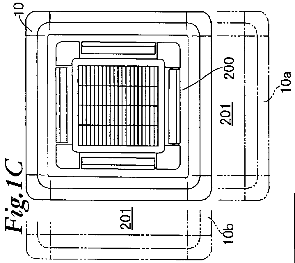
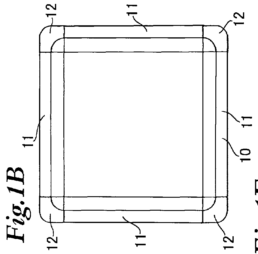
[0107] FIG. 1A shows a ceiling-mounted air-conditioning apparatus 200 mounted in a ceiling surface 201 as viewed from a lower face, i.e. bottom face thereof, FIG. 1B shows a ceiling panel structure 10 according to a preferred embodiment of the invention, and FIG. 1C shows a state where the ceiling panel structure of FIG. 1B is mounted around the air-conditioning apparatus of FIG. 1A.

[0108] The ceiling panel structure 10 comprises four linear panel structures 11, lengths of which are adjustable, and four corner panel structures 12, each connecting the adjacent linear panel structures 11, 11 at respective adjacent ends thereof.

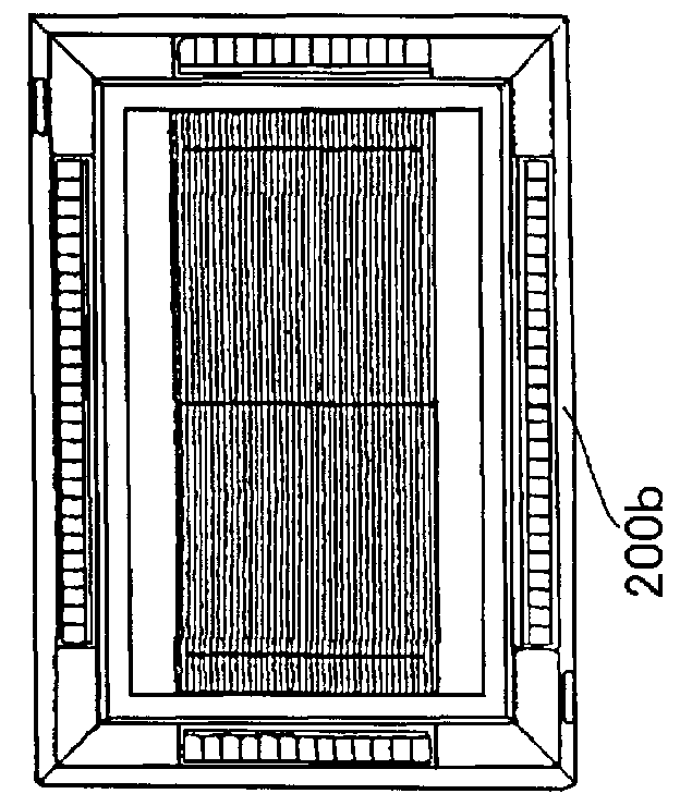
[0109] In a case where the air-conditioning apparatus is of a type 200a having a longitudinally or vertically (in the face of the drawing) elongated rectangular outer shape as shown in FIG. 1E, the ceiling panel stru...


PUM


Abstract

A ceiling panel structure (10; 310) is mounted on a ceiling surface (201) at a downstream of an air-outlet (211) of a ceiling-mounted air-conditioning apparatus (indoor unit) (200) having an air-inlet (210) at a central portion and the conditioning air-outlet (211) at a peripheral portion to minimize the smudging of the ceiling surface and is applicable even to the pre-mounted or existing air-conditioning apparatus. The ceiling panel structure (10; 310) is adapted to be mounted on the ceiling surface (201) at an outside of the air-conditioning apparatus (200) and has a deflection induction portion (47; 347) substantially rigid against the airflow to deflect a part (S1, S2) of the conditioning air, having been blown out through the air-outlet (211) of the air-conditioning apparatus (200), back to the room air-inlet (210). The ceiling panel structure (10; 310) comprises, typically, a base member (20; 320) mounted on the ceiling (201) and a cover member (40; 340) attached to the base member (20; 320) and having portions such as the deflection induction portion (47; 347).

Description

[0001] 1. Field of the Invention[0002] The invention relates to an art for reducing smudging of a ceiling by a conditioning air blown out through an outlet of a ceiling-mounted air-conditioning apparatus (referred to hereinafter also as "ceiling-mounted air-conditioner") or the like.[0003] 2. Description of the Related Arts[0004] An air-conditioning system essentially includes a pair of heat exchangers through which heating / cooling medium is circulated. The air is warmed or heated / cooled when passing through one of the heat exchanger while the medium having been cooled / heated upon warming / cooling the air in said one heat exchanger is heated / cooled at the other heat exchanger. In the air-conditioning system where the pair of heat exchangers are made of separate units, the unit including said one heat exchanger is usually called "indoor unit" or "package type air-conditioner" while the other is called "outdoor unit". The ceiling-mounted air-conditioning apparatus where apparatus is mo...

Claims


Application Information

Patent Timeline
Patent Type & Authority Applications(United States)
IPC IPC(8): F24F1/00F24F13/06
CPCF24F1/0011F24F2001/0037F24F2013/0616F24F1/0047
Inventor HATANAKA, IWAYOSHI
Owner AIR TECHNO
Why Eureka
Try Eureka