Egr cooler

a cooler and cooler technology, applied in the field of coolers, can solve the problems of affecting the heat exchange efficiency of the heat exchanger, affecting the cooling effect of the vehicle, and the high temperature of the tube, so as to achieve the effect of reducing the temperature of the cooler, preventing localized thermal deformation, and effective cooling the sam

Inactive Publication Date: 2006-05-04
HINO MOTORS LTD +2
View PDF4 Cites 31 Cited by
  • Summary
  • Abstract
  • Description
  • Claims
  • Application Information

AI Technical Summary

Benefits of technology

[0025] Thus, since the pitches between the tubes on the center side constituting the respective circles are gradually increased from the outer to inner ones of the circles and the pitches between the circles are also gradually increased from the periphery to the axis of the shell, the cooling water supplied to the shell flows much around the tubes on the center side to effectively cool the same. As a result, localized thermal deformation can be positively prevented to further improve the heat exchange efficiency even if the hot exhaust gas tends to flow much through the tubes on the center side.
[0026] In this case, the central tube may be positioned at the axis of the shell with the pitch between the innermost circle of the tubes and the central tube being made greatest. Thus, since the pitch of the circle on the center side is great to the central tube through which exhaust gas flows most, the cooling water supplied to the shell flows much around the central tube to effectively cool the same. As a result, local thermal deformation can be positively and readily prevented to still further improve the heat exchange efficiency even if the hot exhaust gas tends to flow much through the central tube.

Problems solved by technology

However, such EGR cooler shown in the first example is disadvantageous in that the cooling water 9 supplied via the inlet 4 into the shell 1 nonuniformly flows to the outlet 5 with respect to internal cross section of the shell 1, so that the cooling water 9 may stagnate near corners on opposite sides of the inlet 4 and outlet 5 in the shell 1 as shown by a course 11 to generate cooling water stagnation zones 12, resulting in localized high temperature of and thus thermal deformation of the tubes 3 near the stagnation zones 12.
However, in the second example of the EGR cooler, arrangement of the bypass conduit 14 outside of the shell 1 is disadvantageous in that it interferes with peripheral devices of the shell 1 to substantially lower mountability onto a vehicle.
However, even with the third example of the EGR cooler having the tubes 33 arranged at the constant pitch in the form of concentric circles about the axis O of the shell 31, the hot exhaust gas 40 via the inlet 37 tends to flow more through the tubes 33 on the center side than through the tubes on the peripheral side, so that the tubes 33 on the center side may become higher temperature than those on the peripheral side, resulting in possibility of localized thermal deformation and deteriorated heat exchange efficiency.

Method used


Image

  • Egr cooler
  • Egr cooler
  • Egr cooler

Examples


first embodiment

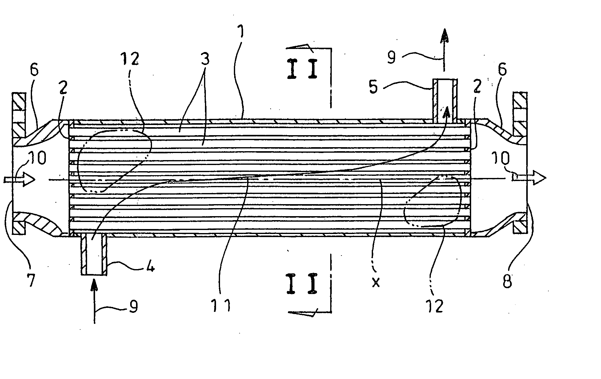
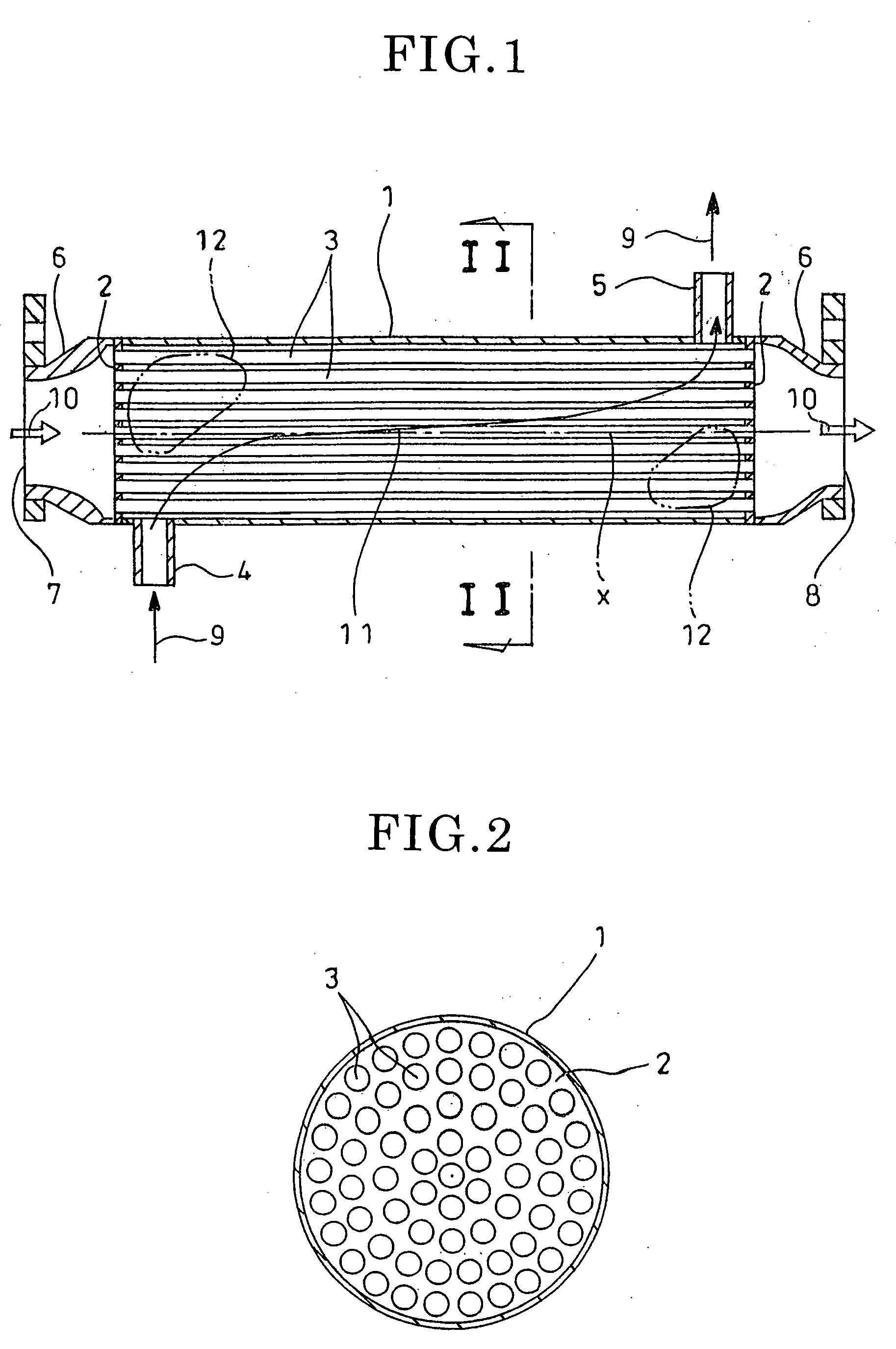
[0043]FIGS. 6 and 7 show the invention in which the parts similar to those in FIGS. 1 to 3 are designated by the same reference numerals.

[0044] In an EGR cooler according to the first embodiment, the number of tubes 3 arranged in a shell 1 is reduced to provide a predetermined inner space 15 on an upper side within the shell 1 defined by an inner surface 1a of the shell 1, plates 2 and the tubes 3. In order to provide a bypass flow path for cooling water 9 in the space 15, a single bypass conduit 16 extends along the axis of the shell 1 and is fixed to the inner surface 1a of the shell 1 by, for example, welding or brazing.

[0045] The conduit 16 has a bypass inlet 16a formed at a position diametrically opposite to a cooling water inlet 4 of the shell 1 and extends axially of the shell 1 as a bypass body 16b into a cooling water outlet 5 via a bent portion 16c to form a bypass outlet 16d midway of the outlet 5. Cross sectional area of the flow path in the conduit 16 is preferably set...

third embodiment

[0054] Now, effects of the second or third embodiment of the invention will be described.

[0055] In this manner, according to the second or third embodiment, the amount of members required for the bypass conduit 19 or 20 is reduced to provide it inexpensively. The second or third embodiment can obtain substantially the same effects and advantages as those in the first embodiment.

fourth embodiment

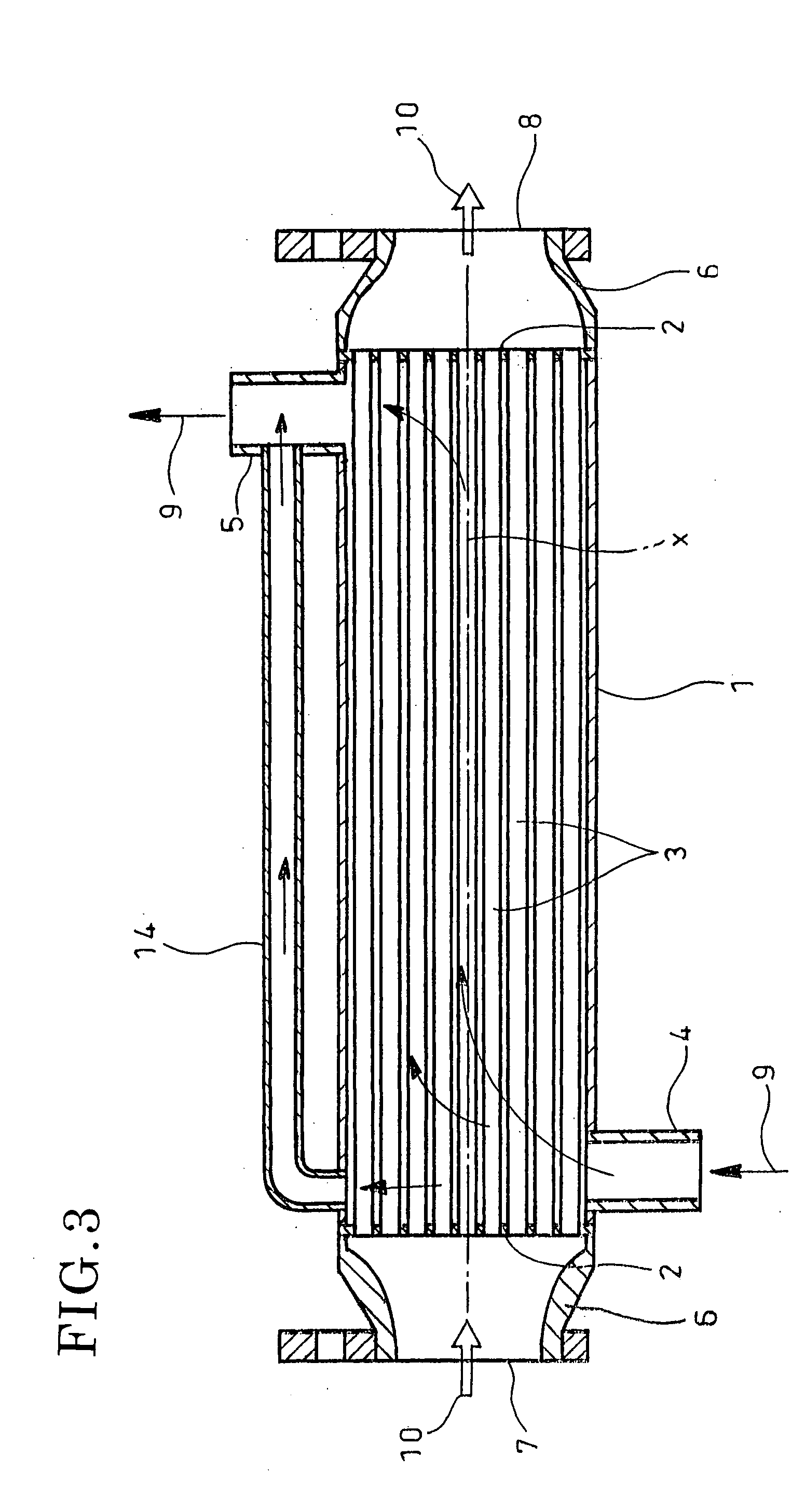
[0056]FIG. 10 shows the invention in which parts similar to those in FIGS. 1 to 3 are designated by the same reference numerals.

[0057] In an EGR cooler according to the fourth embodiment, the number of tubes 3 arranged in a shell 1 is reduced to provide a predetermined inner space 15 on an upper side within the shell 1 defined by an inner surface 1a of the shell 1, plates 2 and the tubes 3, said space 15 serving as a bypass flow path for cooling water 9. Cross sectional area of the flow path in the bypass conduit is preferably set to 5-15% of a total cooling water content substantially as in the case of the first embodiment in accordance with flow analysis, actual device test and the like.

[0058] Now, effects of the fourth embodiment of an EGR cooler according to the invention will be described.

[0059] As shown in the fourth embodiment, when the inner space 15 of the shell 1 formed by reducing the number of the tubes 3 serves as a bypass flow path, the bypass flow path is readily pr...


PUM


Abstract

An EGR cooler including tubes and a shell enclosing the tubes. Cooling water is supplied into and discharged from the shell. Exhaust gas is guided from a diesel engine into the tubes for thermal exchange of the exhaust gas with the cooling water. A bypass flow path for guiding the cooling water is constituted within the shell so as to prevent stagnation of the cooling water in the shell.

Description

TECHNICAL FIELD [0001] The present invention relates to an EGR cooler attached to an EGR apparatus, which recirculates exhaust gas from a diesel engine to suppress generation of nitrogen oxides, so as to cool the exhaust gas to be recirculated. BACKGROUND ART [0002] An EGR apparatus is known which recirculates part of exhaust gas from an engine in a vehicle or the like to the engine to suppress generation of nitrogen oxides. Some of such EGR apparatuses are equipped with, midway of an exhaust gas recirculation line to the engine, an EGR cooler for cooling the exhaust gas since cooling the exhaust gas to be recirculated to the engine will drop the temperature of and reduce the volume of the exhaust gas to lower the combustion temperature in the engine without substantial decrease of output of the engine, thereby effectively suppressing generation of nitrogen oxides. Known in this regard is, for example, JP 2001-74380 A. [0003]FIGS. 1 and 2 are sectional views showing a first example ...

Claims


Application Information

Patent Timeline
Patent Type & Authority Applications(United States)
IPC IPC(8): F28F27/02F02M25/07F28D7/16
CPCF02M25/0714F02M25/0728F02M25/0737F28D7/16F28D21/0003Y02T10/121F02M26/11F02M26/25F02M26/32
Inventor SUGIHARA, HIROYUKITSUJITA, MAKOTOYAMASHITA, YOJIMIWA, NAOTOHONMA, JUNJI
Owner HINO MOTORS LTD
Why Eureka
Try Eureka