

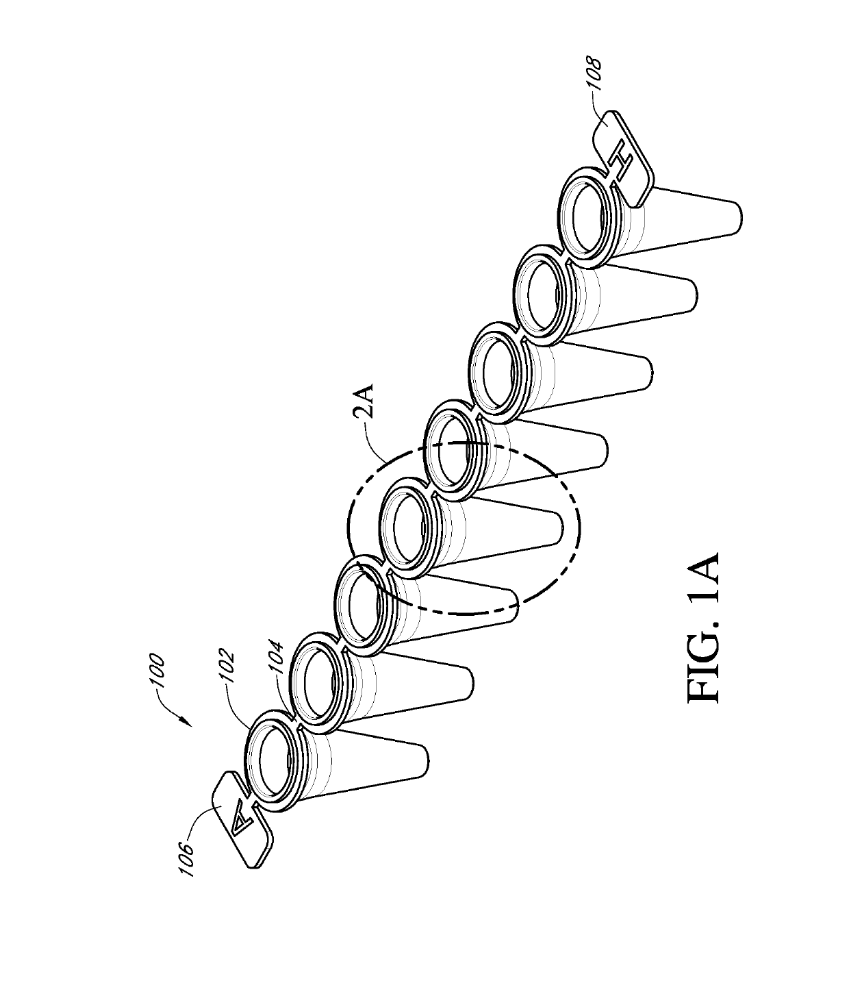
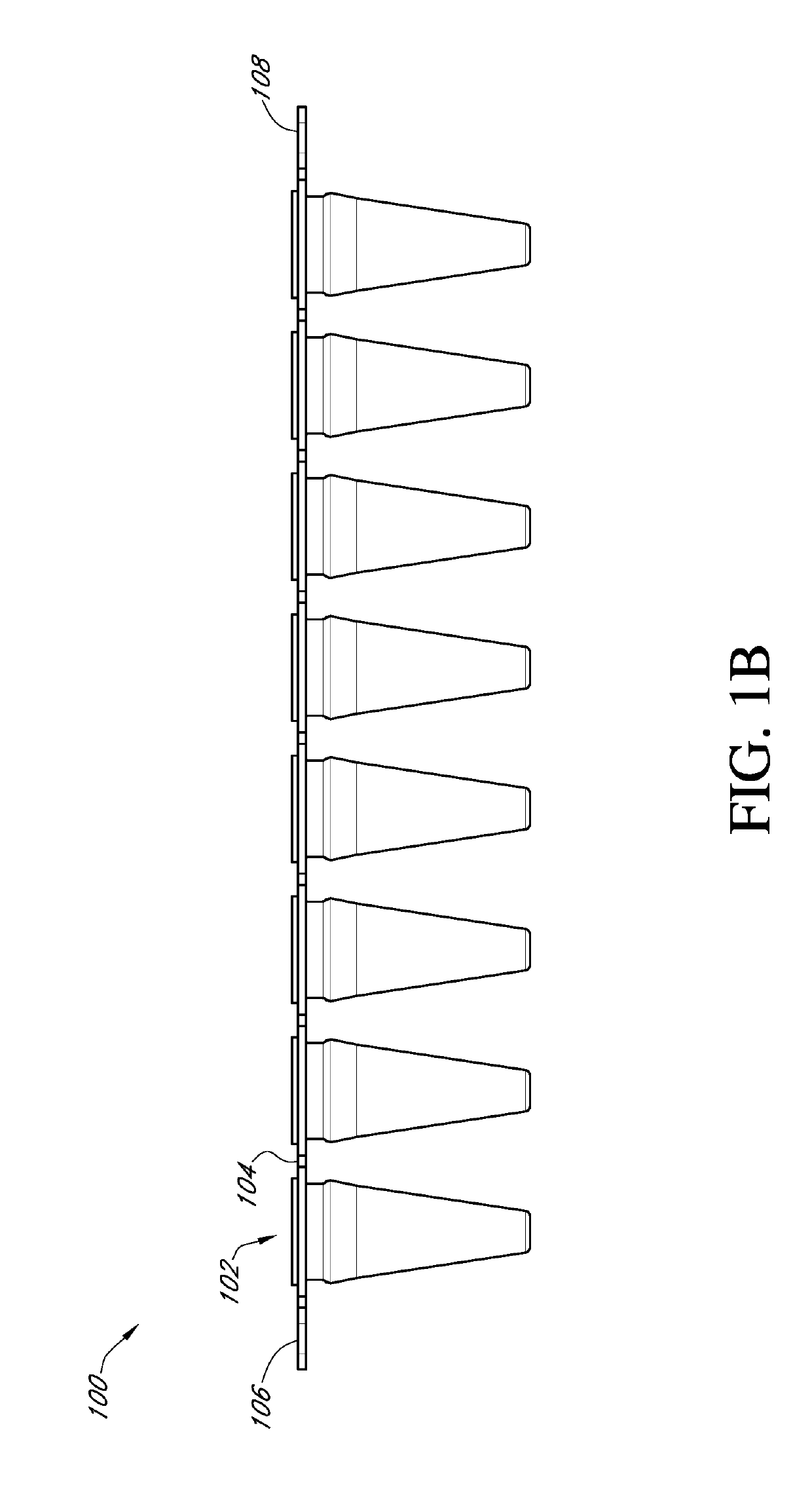
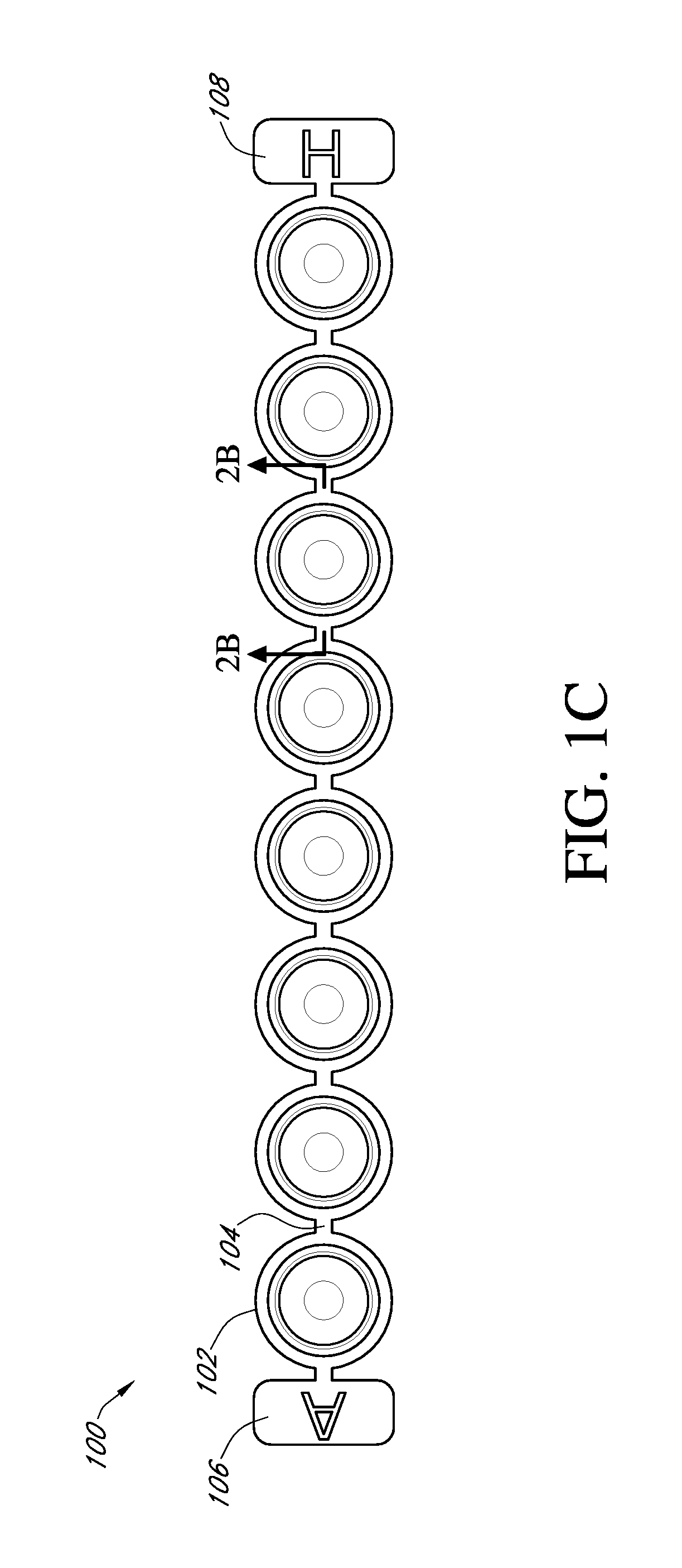
Process tube and carrier tray
a technology which is applied in the field of processing tube and carrier tray, can solve the problems of bottleneck in patient care, no matter what the diagnosis of the patient is, and the time-consuming and labor-intensive step of processing samples for amplification,
- Summary
- Abstract
- Description
- Claims
- Application Information
AI Technical Summary
Benefits of technology
Problems solved by technology
Method used
Image

Examples
example 1
[0086]This example illustrates a specific process for preparing a carrier tray 300 with process tubes 102 to be provided to an end user.[0087]1. Manufacturing 12 process tube strips containing eight connected process tubes formed from polypropylene.[0088]2. Manufacturing a carrier tray from polycarbonate having 96 ports in an 8×12 array.[0089]3. The 12 process tube strips are placed in the carrier tray.[0090]4. The process tubes of the process tube strips are secured in the ports of the carrier tray by applying a force to the top ring of the process tube.[0091]5. Each process tube in the carrier tray is filled with the same specific liquid reagents.[0092]6. The carrier tray is heated to dry the reagents in the process tubes.[0093]7. The process tubes are hot stamped with specific colors to indicate the assay for which they will be used.[0094]8. The carrier tray is stacked and packaged with other carrier trays having the same or different reagents and shipped to the end user.[0095]9....
example 2
[0096]This example describes the test procedure and results of a test to determine the force necessary to secure the process tube strips 100 in the ports 306 of the carrier tray 300 and the force necessary to subsequently remove the process tube strips 100 from the ports 306.
[0097]An Amtek AccuForce Cadet Force Gage, (0-5 lbs) was used to measure the force necessary to secure and remove the process tubes 102 in the ports 306.
[0098]Test Procedure[0099]1. Lay one strip of tubes in a column of the carrier tray. (Not yet secured in the carrier tray)[0100]2. Turn on the gage.[0101]3. Zero the gage with the gage in the upright position.[0102]4. Clear the gage.[0103]5. Slowly press down on each tube within the strip starting at the “A” row with the gage at a slight angle ˜2-3 degrees from vertical on each tube until all the tubes snap into place.[0104]6. Record the force value on the gauge and the column number as insertion values.[0105]7. Press the clear button to clear the memory.[0106]8...
PUM
 Abstract
Description
Claims
Application Information