Methods and apparatus for rotor load control in wind turbines

a technology of wind turbines and load control systems, applied in mechanical equipment, machines/engines, electric generator control, etc., can solve the problems of reducing the power available for load control systems, and affecting the operation of wind turbines. the effect of load reduction

Active Publication Date: 2006-08-22
GENERAL ELECTRIC CO
View PDF29 Cites 70 Cited by
  • Summary
  • Abstract
  • Description
  • Claims
  • Application Information

AI Technical Summary

Benefits of technology

[0006]There is therefore provided, in some configurations of the present invention, a wind turbine having a rotor, at least one rotor blade, and a plurality of generators, of which a first generator is configured to provide power to an electric grid and a second generator is configured to provide power to the wind turbine during times of grid loss. The wind turbine is configured to utilize power provided by the second generator to reduce loads on the wind turbine during times of grid loss.
[0008]Some configurations of the present invention provide a method for reducing load on a wind turbine having a rotor with at least one rotor blade. The method includes using a first generator in the wind turbine to provide electrical power to a power grid. During grid loss conditions, the method includes idling a rotor of the wind turbine, using a second generator in the wind turbine to provide electricity to a pitch control system of the wind turbine, and operating the pitch control system to reduce wind loads on the wind turbine.
[0010]Configurations of the present invention provide an effective control strategy and necessary back-up power to accommodate operation during grid loss conditions when power and control would not otherwise be available. Moreover, by reducing design loads for grid loss conditions, it is possible to provide wind turbines with rotors having larger diameters and thus improved energy capture.

Problems solved by technology

Horizontal wind shears and yaw misalignment, together with natural turbulence, are important causes of asymmetric loads on a wind turbine rotor.
These asymmetric loads together with those from vertical wind shears contribute to extreme loads and the number of fatigue cycles accumulated by a wind turbine system.
However, during grid loss conditions, there is no power available for the load control systems.
It has been difficult to increase rotor diameters to improve wind energy capture because the larger rotors would have to be designed to accommodate the extreme loads and fatigue cycles during times when grid power is lost and no load mitigating active control can be applied.

Method used


Image

  • Methods and apparatus for rotor load control in wind turbines
  • Methods and apparatus for rotor load control in wind turbines
  • Methods and apparatus for rotor load control in wind turbines

Examples


Embodiment Construction

[0015]The present invention is directed to methods and apparatus for efficiently reducing load and providing yaw alignment in wind turbines. Technical effects of the present invention include providing an effective control strategy and necessary back up power to a wind turbine during grid loss conditions and making possible wind turbines with larger rotors than and greater energy capture than is presently possible.

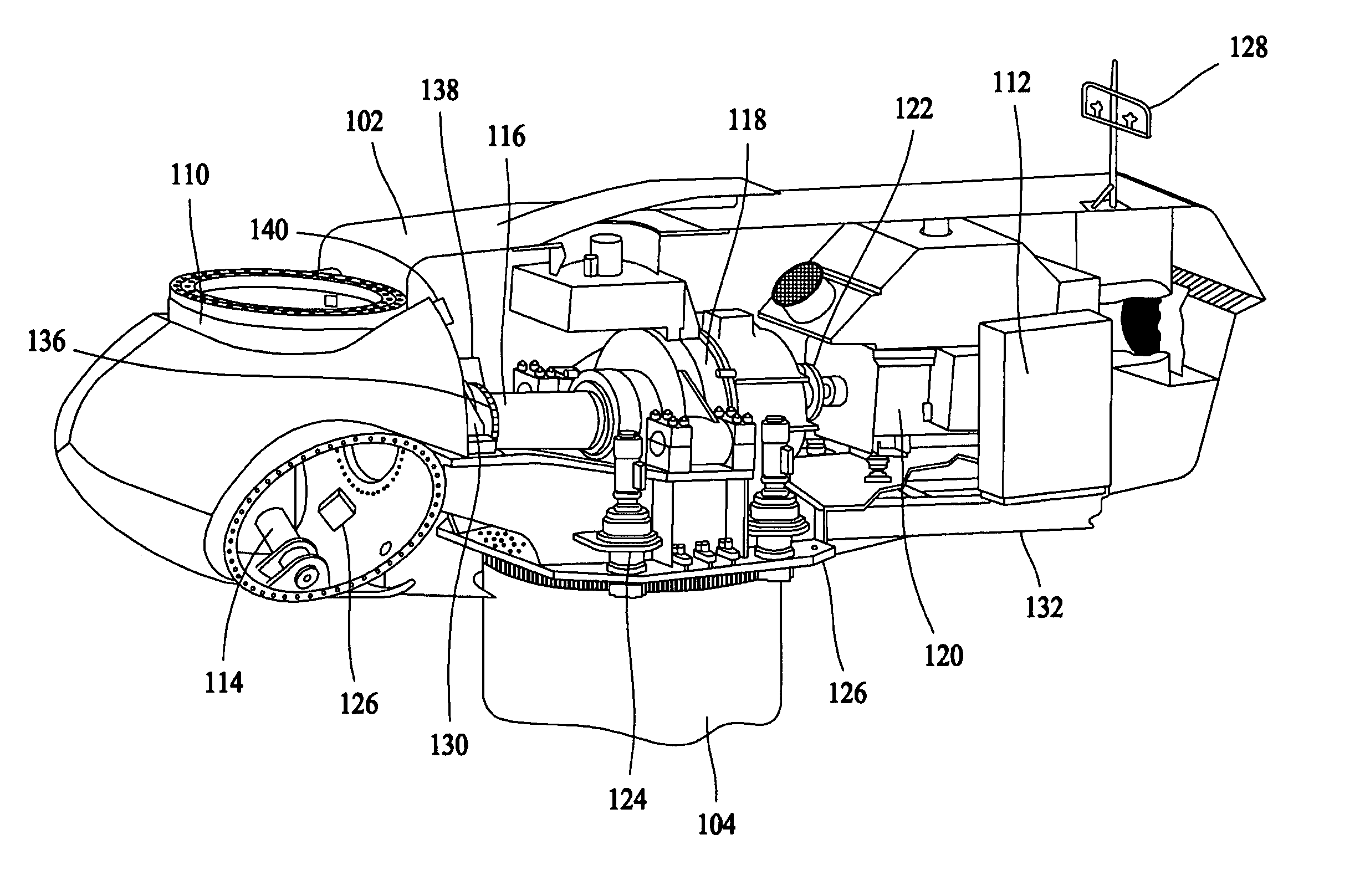
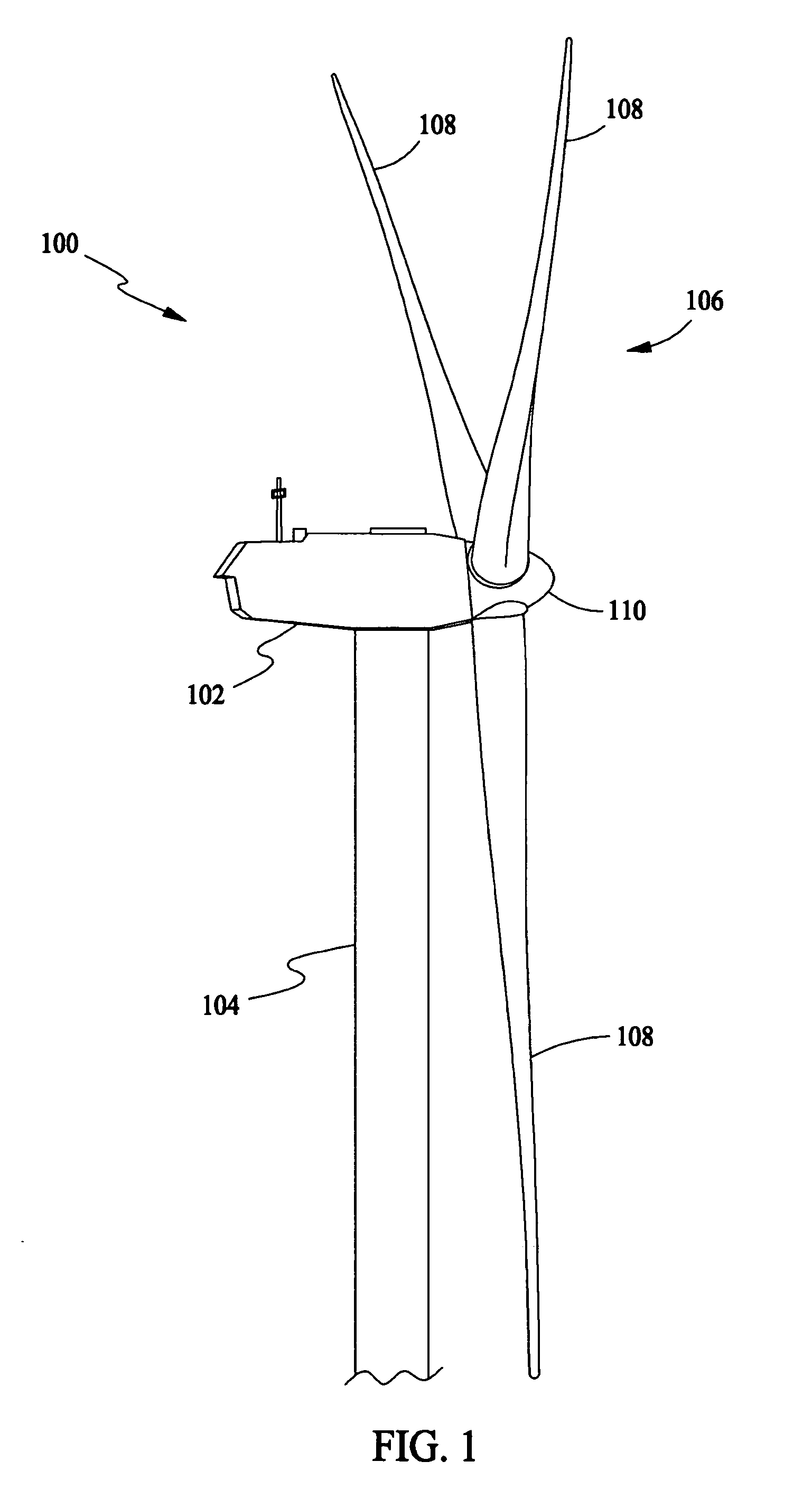
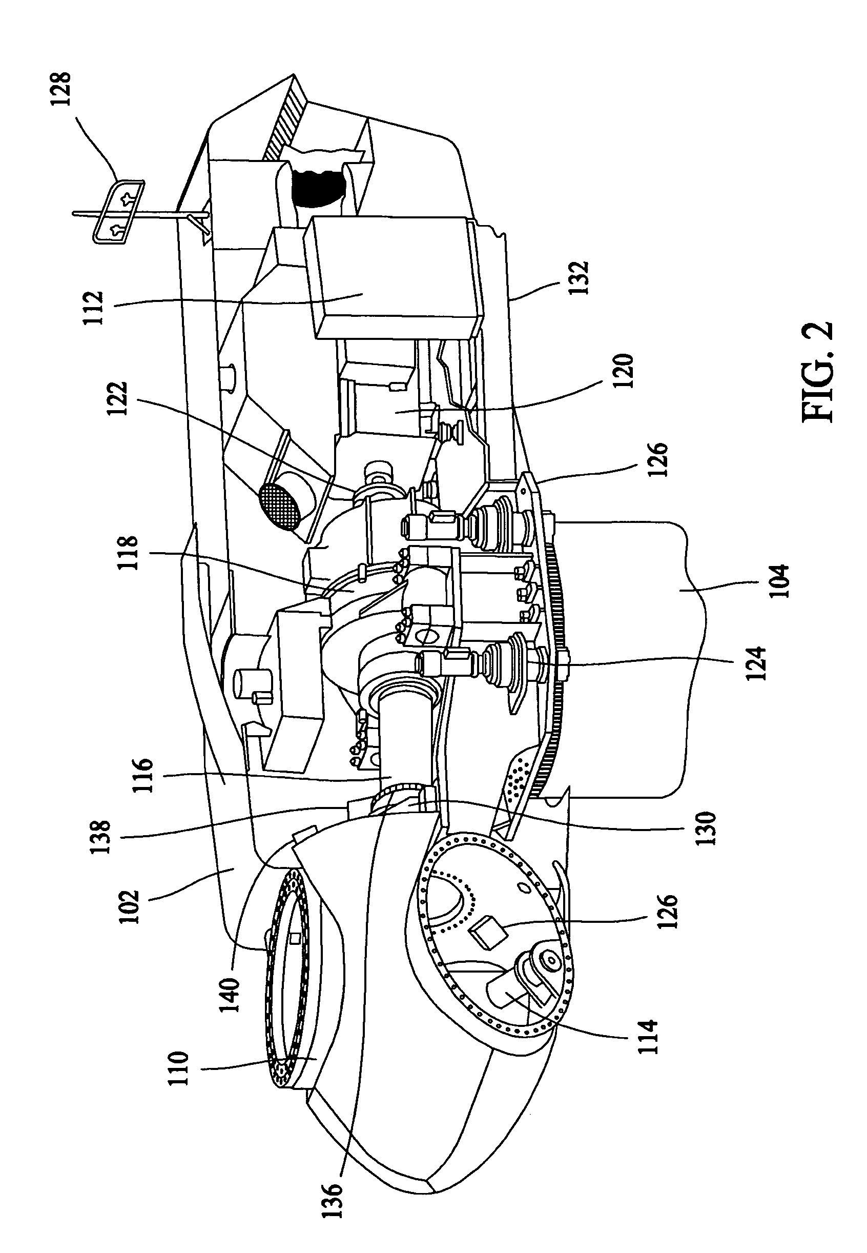
[0016]In some configurations and referring to FIG. 1, a wind turbine 100 in some configurations comprises a nacelle 102 housing a generator (not shown in FIG. 1). Nacelle 102 is mounted atop a tall tower 104, only a portion of which is shown in FIG. 1. Wind turbine 100 also comprises a rotor 106 that includes a plurality of rotor blades 108 attached to a rotating hub 110. Although wind turbine 100 illustrated in FIG. 1 includes three rotor blades 108, there are no specific limits on the number of rotor blades 108 required by the present invention.

[0017]In some configuratio...


PUM


Abstract

A wind turbine having a rotor, at least one rotor blade, and a plurality of generators, of which a first generator is configured to provide power to an electric grid and a second generator is configured to provide power to the wind turbine during times of grid loss. The wind turbine is configured to utilize power provided by the second generator to reduce loads on the wind turbine during times of grid loss.

Description

STATEMENT REGARDING FEDERALLY SPONSORED RESEARCH & DEVELOPMENT[0001]The U.S. Government has certain rights in this invention as provided for by the terms of Contract No. DE-AC36-83CH10093, Subcontract No. ZAM-7-13320-26 awarded by the Department of Energy / Midwest Research Institute, National Renewable Energy Laboratory Division.BACKGROUND OF THE INVENTION[0002]This invention relates generally to wind turbines, and more particularly to methods and apparatus for efficiently reducing load and providing yaw alignment in wind turbines.[0003]Recently, wind turbines have received increased attention as an environmentally safe and relatively inexpensive alternative energy source. With this growing interest, considerable efforts have been made to develop wind turbines that are reliable and efficient.[0004]Generally, a wind turbine includes a rotor having multiple blades. The rotor is mounted on a housing or nacelle, which is positioned on top of a truss or tubular tower. Utility grade wind t...

Claims


Application Information

Patent Timeline
Patent Type & Authority Patents(United States)
IPC IPC(8): F03D9/00
CPCF03D7/0268F03D7/0272H02P9/006H02P2101/15Y02E10/725Y02E10/726Y02E10/723Y02E10/72
Inventor MOROZ, EMILIAN MIECZYSLAW
Owner GENERAL ELECTRIC CO
Why Eureka
Try Eureka