Spring Strut Arrangement for Wheel Suspension of Motor Vehicles

a technology of spring struts and motor vehicles, which is applied in the direction of shock absorbers, mechanical equipment, transportation and packaging, etc., can solve the problems of affecting the length and stroke of the shock absorber, the three-dimensional and functionally reliable arrangement of the positioning drive integrated on the spring strut within the preloaded spring, and the loss of valuable installation space. , to achieve the effect of reducing weigh

Inactive Publication Date: 2010-12-09
AUDI AG
View PDF12 Cites 43 Cited by
  • Summary
  • Abstract
  • Description
  • Claims
  • Application Information

AI Technical Summary

Benefits of technology

[0006]According to the invention, it is proposed that the shock absorber with the absorber tube be located toward the top on the vehicle body and that the positioning spindle of the positioning drive be pivoted on the absorber tube. This yields a structurally especially durable and compact construction of the integrated positioning drive with reduced cost of parts, since the guide sleeve required in the generic design for the positioning spindle can be omitted without replacement. Furthermore, in this way the positioning drive can be made with a smaller outside diameter; this improves the installation situation of the entire spring strut with the suspension spring and preloaded spring in the motor vehicle.

Problems solved by technology

The three-dimensional and functionally reliable arrangement of the positioning drive integrated on the spring strut within the preloaded spring is a problem, however, especially for wheel suspensions with steered wheels in which the wheel requires a corresponding free space in the wheel well and for the wheel suspension elements.
Valuable installation space is lost, however, by lining up the elongated bearing bush with its lower bearing arrangement.
This has an adverse effect on the shock absorber length and on the shock absorber stroke.
Moreover, the total weight of the spring strut is increased by the long piston rod which is required in this design and the long bearing bush.
This can lead to contact between the oscillating shock absorber and the rotating spindle.
This would, however, lead to a relatively large spindle diameter, as a result of which, however, the rotational mass moment of inertia of the spindle is adversely increased.

Method used


Image

  • Spring Strut Arrangement for Wheel Suspension of Motor Vehicles
  • Spring Strut Arrangement for Wheel Suspension of Motor Vehicles
  • Spring Strut Arrangement for Wheel Suspension of Motor Vehicles

Examples


Embodiment Construction

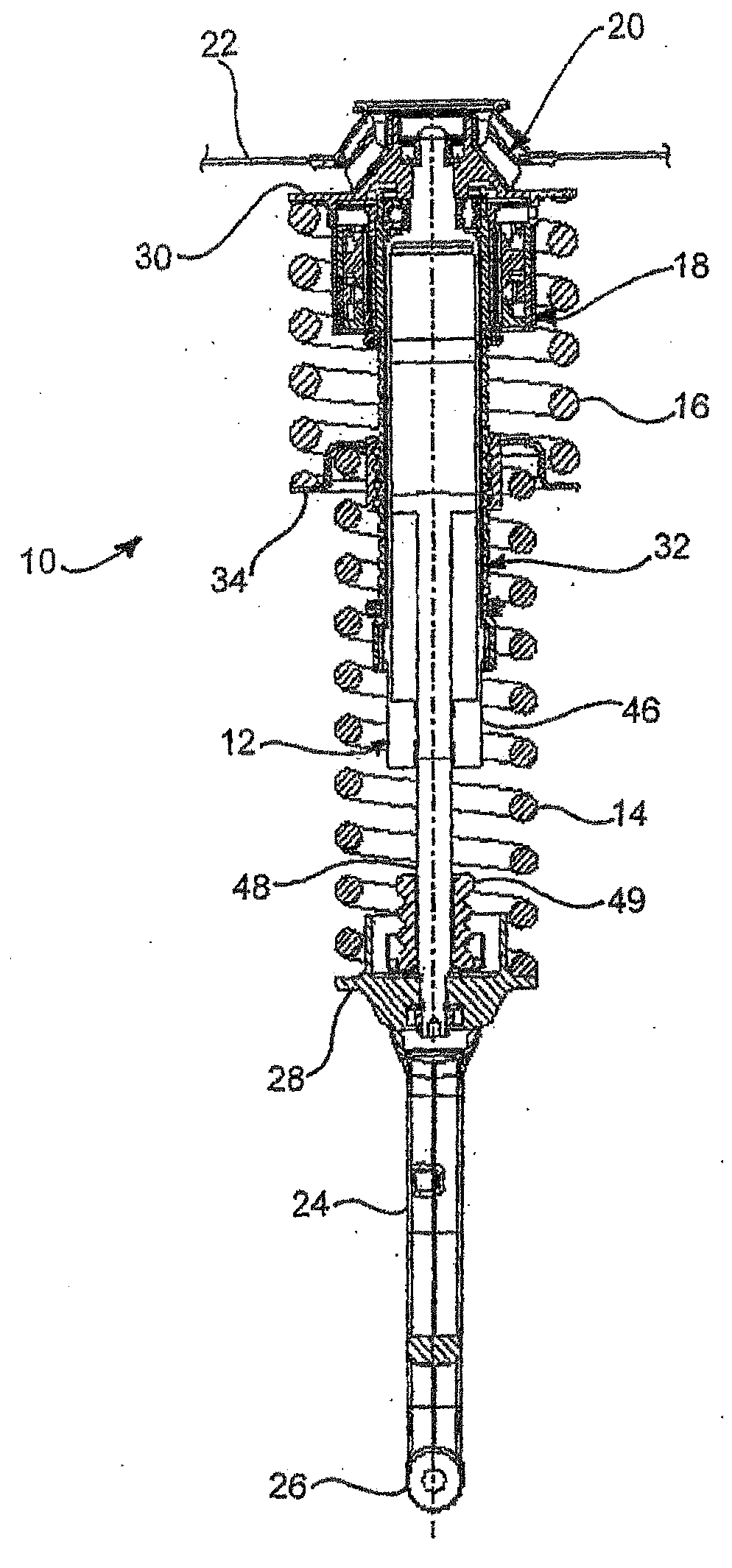
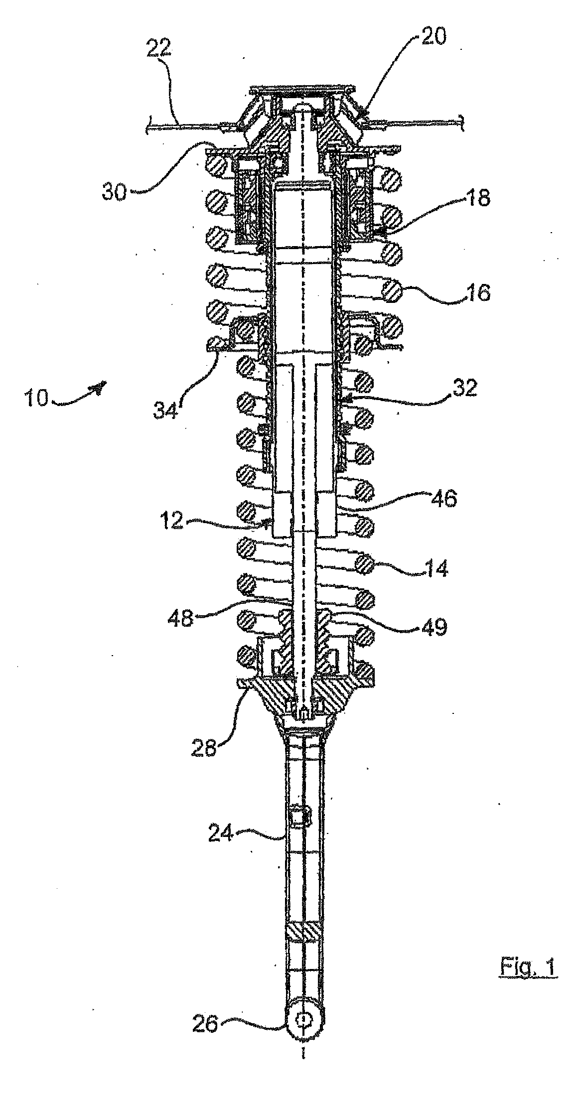
[0032]The spring strut 10 as shown in FIG. 1 has essentially a telescoping shock absorber 12, a suspension spring 14, a preloaded spring 16, and an electromechanical actuator 18.

[0033]The spring strut 10 on its upper end is coupled to the body 22 (only suggested) of the motor vehicle by way of an annular, rubber-elastic shock absorber bearing 20. The lower end of the spring strut 10 is articulated by way of a support brace 24 and a rubber-metal sleeve joint 26 to a wheel suspension element, for example a connecting rod or a wheel carrier.

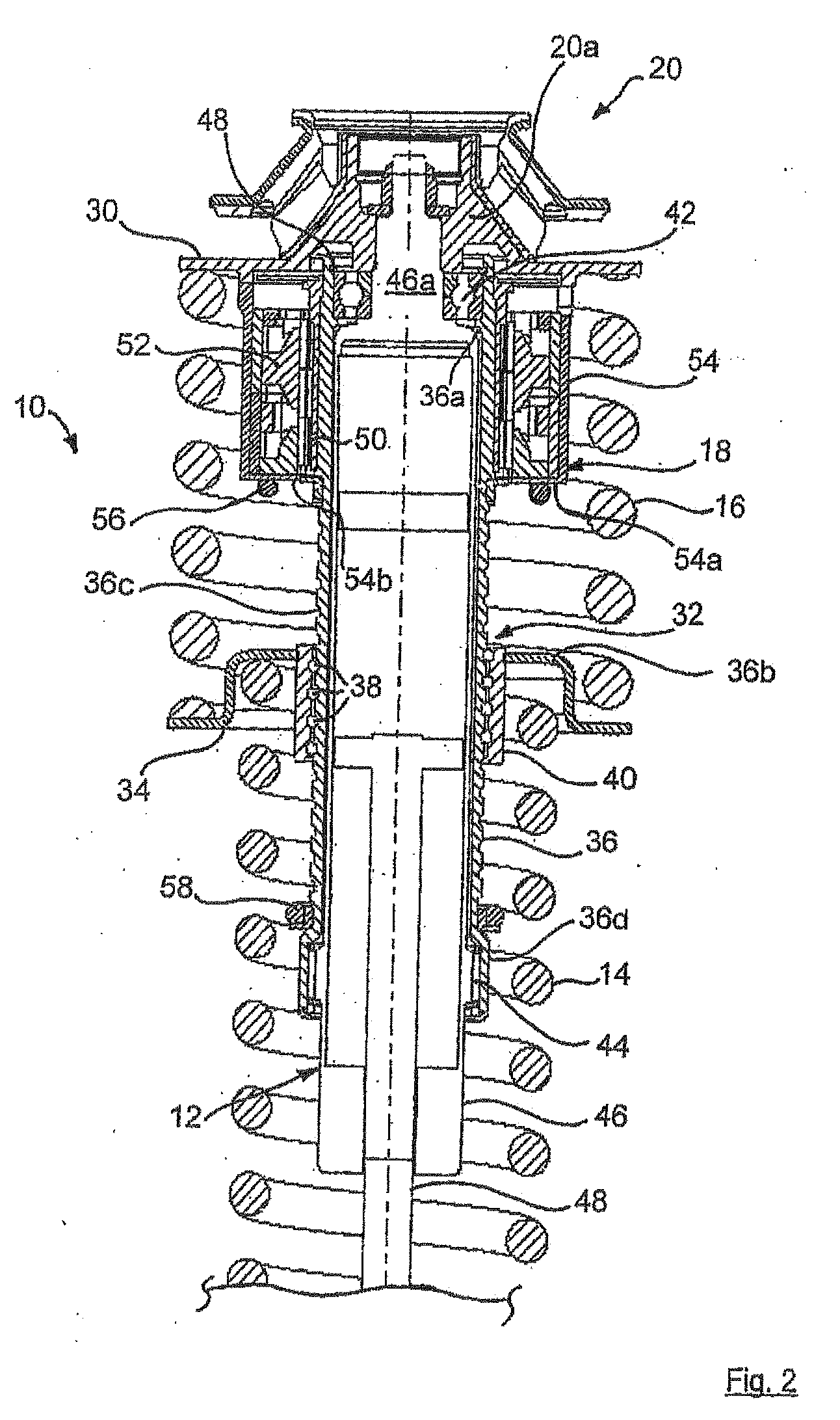
[0034]The suspension spring 14 and the preloaded spring 16 are made as helical compression springs, as is apparent, and are supported on the support brace 24 and on the body 22 by way of spring caps 28, 30. Between the suspension spring 14 and the preloaded spring 16, there is an adjustable spring cap 34 which can be moved axially by way of a positioning drive 32 and on which the suspension spring 14 and the preloaded spring 16 are supported, connec...


PUM


Abstract

The invention relates a spring strut arrangement for wheel suspensions of motor vehicles, which is formed from a telescoping shock absorber, a suspension spring element which is preferably made as a helical compression spring, and a preloaded spring element which is preferably made as a helical compression spring, the spring elements being supported by way of spring caps on the body of the motor vehicle and on a wheel suspension element and a third spring cap located in between being movably guided along the longitudinal axis of the shock absorber relative to the body by way of an electrically driven positioning drive which is located within the spring elements, the positioning drive having a positioning spindle which is pivoted around the shock absorber and an adjusting nut which is connected to the movable spring cap. According to the invention, the shock absorber with the shock absorber tube is located at the top on the body of the motor vehicle and the positioning spindle is pivoted on the shock absorber tube.

Description

[0001]The invention relates to a spring strut arrangement for wheel suspensions of motor vehicles.BACKGROUND OF THE INVENTION[0002]Various hydraulic, hydraulic / pneumatic, and fully electrical systems with all-electrical actuators are known for active vertical adjustment of a motor vehicle. An active “spring strut” that is suitable for this vertical adjustment has a suspension spring and a preloaded spring which are each separated by an adjustable spring cap. The adjustable spring cap is exposed to positioning forces during vertical adjustment. That is, the adjustable spring cap as needed traverses an axial path dictated by the control, and thus ultimately produces a positioning force on the wheel. The lifting motion of the adjustable spring cap takes place almost exclusively by a ball groove thread drive in which the adjustable spring cap does not rotate during its lifting motion, but remains torsionally strong, while the relatively slender spindle of the ball groove thread drive ro...

Claims


Application Information

Patent Timeline
Patent Type & Authority Applications(United States)
IPC IPC(8): B60G17/02B60G17/015F16F13/00F16F15/06F16F15/023B60G15/06
CPCB60G15/068B60G17/021B60G2202/312F16F9/56B60G2204/12422B60G2500/30F16F1/121B60G2204/124F16F3/04
Inventor MICHEL, WILFRIED
Owner AUDI AG
Why Eureka
Try Eureka