Light source assembly and projection device

A technology of light source components and light components, which is applied in the field of projection, can solve problems such as large area, loss of fluorescence, and low light collection efficiency of light source components, and achieve the effects of increasing area, reducing area, and improving light collection efficiency

Pending Publication Date: 2021-09-07
QINGDAO HISENSE LASER DISPLAY CO LTD
View PDF6 Cites 3 Cited by
  • Summary
  • Abstract
  • Description
  • Claims
  • Application Information

AI Technical Summary

Problems solved by technology

The transmission area is often set as a dichroic mirror. In order to allow the excitation beam to pass through the transmission area, the area of ​​the transmission area is often relatively large. An excessively large area of ​​the transmission area will cause the fluorescence emitted by the wavelength conversion device to be lost in this area, resulting in the loss of light source components. The light collection efficiency is low

Method used


Image

  • Light source assembly and projection device
  • Light source assembly and projection device
  • Light source assembly and projection device

Examples


Embodiment Construction

[0034] In order to make the purpose, technical solutions and advantages of the embodiments of the present application clearer, the following will further describe the embodiments of the present application in detail in conjunction with the accompanying drawings.

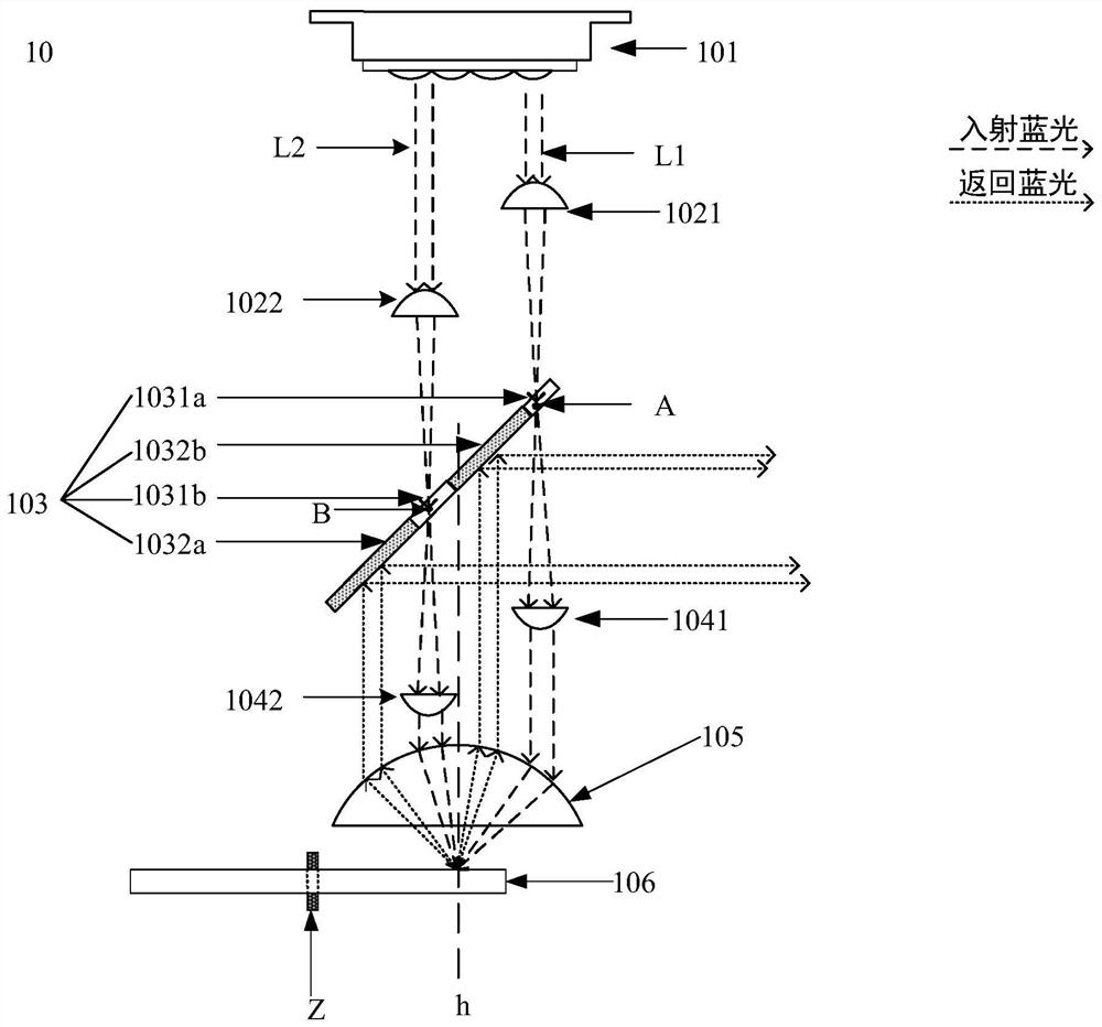
[0035] Such as figure 1 as shown, figure 1 A schematic diagram of an embodiment of the present application is shown. As shown in the figure, the light source assembly 10 includes:

[0036] Laser 101, used to emit two beams of excitation light: a first beam and a second beam;

[0037] The first lens group 102 includes a first lens and a second lens. Both the first lens and the second lens are convex lenses. The two beams are reduced;

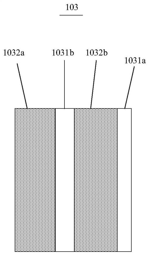
[0038] The light combination component 103 includes a transmission area and a reflection area, wherein the transmission area includes a first transmission area 1031a and a second transmission area 1031b, and the two beams of light emitted by the laser 101 respectively transmit the f...


PUM


Abstract

The embodiment of the invention discloses a light source assembly and a projection device, and belongs to the technical field of projection. The light source assembly comprises a laser for emitting a first light beam and a second light beam; a light combination assembly which comprises a reflection area and a transmission area, wherein the transmission area comprises a first transmission area and a second transmission area; the first light beam sequentially passes through a first lens, the first transmission area and a third lens and enters a third lens group; the second light beam sequentially passes through a second lens, the second transmission area and a fourth lens and enters the third lens group; the third lens group converges the incident first light beam and the incident second light beam and emits the light beams to a wavelength conversion device; and the wavelength conversion device which reflects or converts the incident light beam into fluorescent light and emits the fluorescent light to the third lens group, wherein the third lens group collimates the light beam and then emits the light beam to a reflection area of the light combination assembly, and the light beam is reflected to a light emitting direction by the reflection area. According to the embodiment of the invention, the light receiving efficiency of the light source assembly is improved.

Description

technical field [0001] The embodiments of the present application relate to the field of projection technology, and in particular, to a light source component and a projection device. Background technique [0002] With the continuous development of science and technology, projection equipment is more and more used in people's work and life. At present, the projection equipment mainly includes a light source system, an optomechanical system and a lens. After the light beam is processed, it is emitted to the lens, so that the lens can emit the light beam to the projection screen, and then realize the display of the picture on the projection screen. [0003] In the related art, the light source assembly includes a laser for emitting excitation light; the light combination assembly includes a reflection area and a transmission area; a wavelength conversion device is used to emit or accept the excitation light incident to the wavelength conversion device. Excited to fluoresce. ...

Claims


Application Information

Patent Timeline
Patent Type & Authority Applications(China)
IPC IPC(8): G03B21/20G02B27/10
CPCG03B21/206G03B21/204G03B21/2066G02B27/10
Inventor 颜珂李巍
Owner QINGDAO HISENSE LASER DISPLAY CO LTD
Why Eureka
Try Eureka