Novel-structure horizontal machining center machine tool

A machining center and new structure technology, applied in the direction of metal processing machinery parts, metal processing equipment, manufacturing tools, etc., can solve the problems of cumbersome installation, high casting difficulty, large overall area of ​​the base, etc., to reduce the difficulty of installation process, production casting The effect of simplicity, convenience and simplification of the overall structure

Pending Publication Date: 2022-01-11
L K PRECISION MACHINERY KUNSHAN
View PDF0 Cites 0 Cited by
  • Summary
  • Abstract
  • Description
  • Claims
  • Application Information

AI Technical Summary

Problems solved by technology

[0003] At present, the bed structure of the conventional horizontal machining center is complex, the internal support ribs of the base are distributed in a mesh shape, the casting difficulty is relatively high, and the overall area of ​​the base is large, resulting in a large number of bed foundations, complicated installation and debugging process, and time-consuming and laborious;

Method used


Image

  • Novel-structure horizontal machining center machine tool
  • Novel-structure horizontal machining center machine tool
  • Novel-structure horizontal machining center machine tool

Examples


Embodiment Construction

[0030] The following will clearly and completely describe the technical solutions in the embodiments of the present invention with reference to the drawings in the embodiments of the present invention.

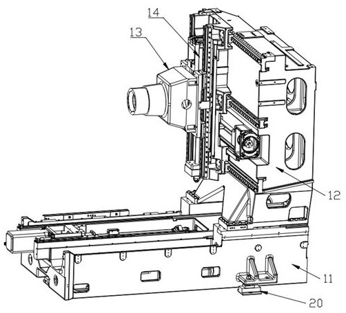
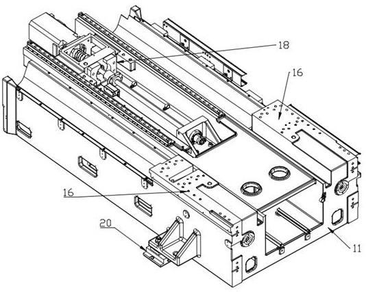
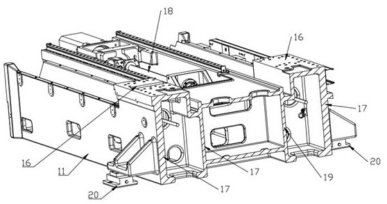
[0031] see Figure 1-8 , in an embodiment of the present invention, a horizontal machining center machine tool with a new structure includes a base 11, a column 12, a headstock 13 and a saddle 14, a line rail 15 is fixedly installed on the upper end of the base 11, and a force-receiving part is arranged on the upper end of the base 11 16. The column 12 is fixedly installed above the force-receiving part 16. A reinforcing rib 17 is provided under the force-receiving part 16. The force-receiving part 16 is supported by the reinforcing rib 17. The left end surface of the column 12 is slidably installed with a saddle 14. The front end of the column 12 is provided with a screw part 18, and the column 12 controls the movement of the saddle 14 through the screw part 18. The front end...


PUM


Abstract

The invention discloses a novel-structure horizontal machining center machine tool in the field of horizontal machining centers. The machine tool comprises a base, a stand column, a spindle box and a sliding saddle, a stress part is arranged at the upper end of the base, the stand column is fixedly mounted above the stress part, a reinforcing rib is arranged below the stress part, the sliding saddle is slidably mounted on the left end face of the stand column, the spindle box is slidably mounted on the front end face of the sliding saddle, and the sliding saddle controls the spindle box to move through a lead screw part in front of the sliding saddle. By means of the structure, the problems that due to the fact that a conventional horizontal machining center lathe bed is complex in structure, supporting ribs in a base are distributed in a net shape, casting difficulty is higher, the overall area of the base is larger, the number of lathe bed foundations is large, the installation and debugging process is complex, time and labor are wasted, a huge structure and low rigidity in the X axis direction exist in stand column and sliding saddle hollow frame type horizontal machining, a three-axis lead screw bearing of a traditional horizontal machining center usually selects an angular contact ball bearing, the bearing needs to be used in a matched manner, the number of bearings is large, installation accessories are many and complex, and installation is tedious exist are solved.

Description

technical field [0001] The invention relates to the field of horizontal machining centers, in particular to a horizontal machining center machine tool with a new structure. Background technique [0002] The horizontal machining center is a machine tool that realizes milling through the mechanism of the horizontal layout of the spindle. Due to the horizontal layout of the spindle, the tool reciprocates along the side of the workpiece to promote the effective discharge of chips. The quality and performance of the CNC machine tool are stable and reliable, suitable for national conditions and widely used. [0003] At present, the bed structure of the conventional horizontal machining center is complex, the internal support ribs of the base are distributed in a mesh shape, the casting difficulty is relatively high, and the overall area of ​​the base is large, resulting in a large number of bed foundations, complicated installation and debugging process, and time-consuming and labo...

Claims


Application Information

Patent Timeline
IPC IPC(8): B23Q1/01B23Q11/00B23Q5/40
CPCB23Q1/015B23Q11/0032B23Q5/40
Inventor 刘英良王鹏黄小发伍会
Owner L K PRECISION MACHINERY KUNSHAN
Why Eureka
Try Eureka