A cutting fluid recovery device for CNC machine tools

A recovery device and a technology of CNC machine tools, which are applied in the direction of metal processing machinery parts, metal processing equipment, maintenance and safety accessories, etc., can solve the problems of difficult cleaning of debris, affecting the flow of cutting fluid, and blockage, so as to improve the interception effect and facilitate cleaning effect

CN114131424BActive Publication Date: 2022-07-26江苏益铨数控科技有限公司
7 Cites 2 Cited by

Patent Information

Authority / Receiving Office
CN · China
Patent Type
Patents(China)
Current Assignee / Owner
Publication Date
2022-07-26

Smart Images

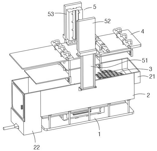
  • Figure 1
    Figure 1
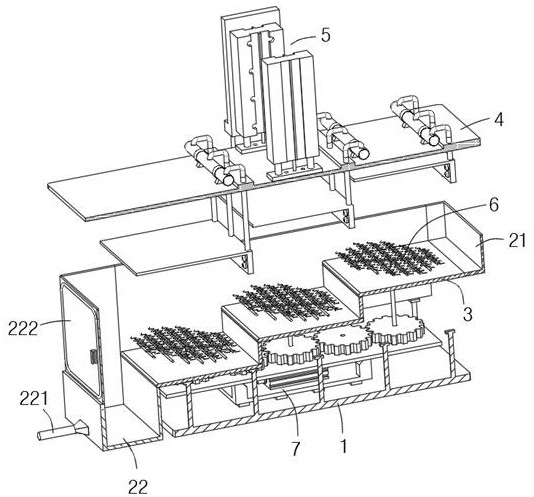
  • Figure 2
    Figure 2
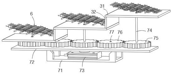
  • Figure 3
    Figure 3
Patent Text Reader

Abstract

The invention discloses a cutting fluid recovery device for a numerically controlled machine tool, and relates to the technical field of cutting fluid recovery. Including a frame, the top of the frame is installed with two side plates, the two side plates are arranged in parallel, and a baffle plate assembly is arranged between the two side plates, and the two ends of the baffle plate assembly are respectively connected to the side plates of the side plate. Both ends are flush; the guide plate assembly includes several guide plates, which are arranged in parallel and are arranged in a stepped shape from bottom to top, and a guide plate is connected between two adjacent guide plates. The vertical plate, the guide plate and the two sides of the guide vertical plate are respectively in contact with the inner sides of the two side plates; one end of the guide plate assembly is provided with a liquid inlet box, and the other end is provided with a liquid discharge box, and the liquid inlet box, The tops of the liquid discharge box and the side plate are flush, and a discharge pipe is installed on the liquid discharge box; an intercepting mechanism is respectively provided above each guide plate. The invention has the advantages of being convenient for retaining debris, convenient for recycling processing of cutting fluid and cleaning of debris.
Need to check novelty before this filing date? Find Prior Art

Description

technical field

[0001] The invention relates to the technical field of cutting fluid recovery, in particular to a cutting fluid recovery device for CNC machine tools. Background technique

[0002] CNC machine tool is a kind of equipment that can be used for drilling, cutting, forging and other operations on workpieces. When CNC machine tools are cutting, they are generally used with cutting fluid, and many strips of different lengths will be generated during work. , and when the cutting fluid is recovered, the cutting fluid will be mixed with short strip-shaped debris, and the debris needs to be filtered.

[0003] Existing recycling devices mostly use filter screens, filter plates, etc. to intercept and filter debris. Because the strip-shaped debris is easy to get stuck in the filter holes, it is easy to cause blockage and also affect the flow of cutting fluid. Chips are not easy to clean. SUMMARY OF THE INVENTION

[0004] The purpose of the present invention is to provi...

Examples

Embodiment Construction

[0029] The technical solutions in the embodiments of the present invention will be clearly and completely described below with reference to the accompanying drawings in the embodiments of the present invention. Obviously, the described embodiments are only a part of the embodiments of the present invention, rather than all the embodiments. Based on the embodiments of the present invention, all other embodiments obtained by those of ordinary skill in the art without creative efforts shall fall within the protection scope of the present invention.

[0030] see Figure 1-Figure 10 , The present invention provides a technical solution: a cutting fluid recovery device for a numerically controlled machine tool, comprising a frame 1, two side plates 2 are installed on the top of the frame 1, the two side plates 2 are arranged in parallel, and the two side plates 2 are arranged in parallel. A deflector assembly 3 is arranged between the two ends of the deflector assembly 3, and both e...