Shell structure of moisture removal device of clothes dryer, moisture removal device and clothes dryer

A technology for clothes dryers and shells, which is applied in the field of clothes dryers, and can solve the problems such as the environmental humidity and temperature of clothes dryers are greatly affected, and achieve the effect of simplifying the connection of pipes

Pending Publication Date: 2022-04-08
YUNMI HULIAN TECH (GUANGDONG) CO LTD
View PDF0 Cites 0 Cited by
  • Summary
  • Abstract
  • Description
  • Claims
  • Application Information

AI Technical Summary

Problems solved by technology

[0003] At present, the clothes dryers on the market are heated by heaters to form hot air, and the hot air is passed into the drying drum through the fan. The hot air can take away the moisture on the surface or inside of the wet clothes, and then dry the wet clothes, and the formed damp

Method used


Image

  • Shell structure of moisture removal device of clothes dryer, moisture removal device and clothes dryer
  • Shell structure of moisture removal device of clothes dryer, moisture removal device and clothes dryer
  • Shell structure of moisture removal device of clothes dryer, moisture removal device and clothes dryer

Examples


Embodiment 1

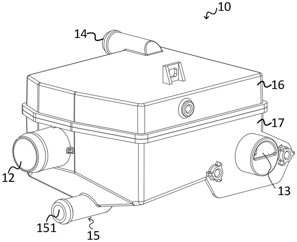
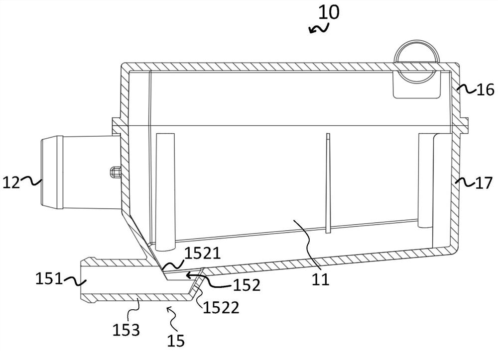
[0051] The present invention provides a shell structure of a dehumidification device for a clothes dryer, which includes an outer surface shell 10 for forming a dehumidification device body 1 disposed in the main body of the clothes dryer; Figure 1 to Figure 5 As shown, the housing 10 includes:

[0052] The cavity 11 is used to accommodate the heat exchange element 20; the cavity 11 is also used to form a temporary storage space for the hot and humid air. After the hot and humid air enters the cavity 11, the flow speed of the hot and humid air is reduced due to the constraint of the contour of the cavity 11 , so that the hot and humid air is temporarily gathered in the cavity 11 to contact the heat exchange element 20 in the cavity 11;

[0053] The air inlet 12 is used to pass into the cavity 11 the hot and humid air generated by the drying drum of the dryer body;

[0054] The air outlet 13 is used to discharge the hot and humid air to the outside of the dryer body after bei...

Embodiment 2

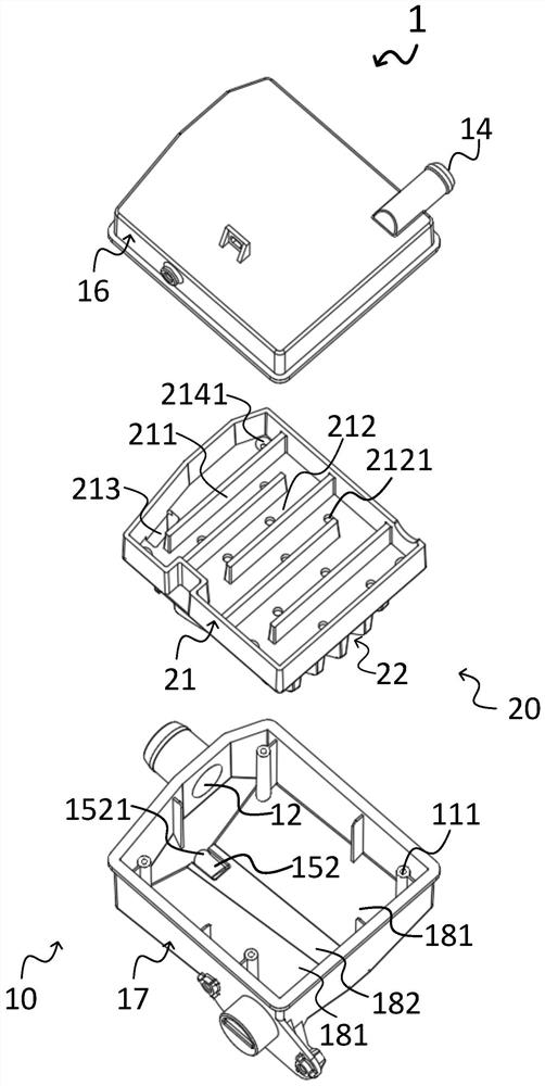
[0068] The invention provides a dehumidification device, such as figure 1 , image 3 , Figure 4 , Figure 5 As shown, it includes a dehumidification device body 1 arranged in the clothes dryer body, and the dehumidification device body 1 includes:

[0069] The casing 10 as described above; the casing 10 is provided with a cavity 11 for accommodating the heat exchange element 20 , an air outlet 13 , and a drainage pipe 15 ; the heat exchange element 20 is arranged in the cavity 11 of the casing 10 ;

[0070]The heat exchange element 20 is used to cool the hot and humid air in the cavity 11; the heat exchange element 20 is arranged in the cavity 11; the hot and humid air in the drying drum of the clothes dryer body enters the cavity 11, and the heat exchange element 20 absorbs The heat of hot and humid air is condensed during the cooling process of hot and humid air to form condensed water for dehumidification. The cooled and dehumidified air is discharged to the outside of ...

Embodiment 3

[0107] The present invention provides a clothes dryer, which includes a clothes dryer body for performing drying, and the clothes dryer body includes the moisture draining device body 1 of a moisture draining device for a clothes dryer as described above. The main body of the clothes dryer includes a cabinet and a drying cylinder; the drying cylinder and the dehumidification device body 1 are all arranged in the cabinet, and the air outlet 13 of the dehumidification device body 1 is in one-way communication with the external environment of the cabinet, so as to seal the cavity The hot and humid air in 11 is discharged out of the casing after being cooled and dehumidified. When the dryer body executes the drying program, the hot and humid air in the drying cylinder is passed into the cavity 11 from the air inlet 12, and after being cooled by the cooling part 21, the moisture in the hot and humid air is condensed and removed, and then discharged from the air outlet 13 Outside th...


PUM


Abstract

The invention provides a shell structure of a moisture removal device of a clothes dryer, and a shell comprises a cavity for accommodating a heat exchange piece; the air inlet is used for introducing humid and hot air generated by a clothes drying cylinder of the clothes dryer body into the cavity; the air outlet is used for discharging the humid and hot air which is cooled and dehumidified by the heat exchange piece out of the clothes dryer body; a drainage pipeline; and a water outlet of the drainage pipeline extends out of the side wall of the shell so as to discharge condensate water formed in the cooling process of wet and hot air in the cavity from the side edge of the shell. The invention further provides a moisture removal device and a clothes dryer. Due to the fact that the size and the position of the clothes drying cylinder are determined, the moisture removal device body is usually installed in the space on the peripheral side of the clothes drying cylinder, and the water outlet of the drainage pipeline extends out of the side wall of the shell, the drainage pipeline of the moisture removal device body can be conveniently communicated with a component located on the side of the moisture removal device body, corresponding pipeline connection is simplified, and the moisture removal efficiency is improved. And the situation that the space occupied by the connecting pipeline in the clothes dryer body is increased due to bending of the connecting pipeline is avoided.

Description

technical field [0001] The invention relates to the technical field of household electrical appliances, in particular to a shell structure of a dehumidification device for a clothes dryer, a dehumidification device and a clothes dryer. Background technique [0002] With the improvement of people's living standards, users' requirements for clothes dryers are not only for cleaning. Due to weather factors, such as the rainy season, it takes a long time to dry clothes after washing. Some users also need clothes dryers that can dry clothes. . [0003] At present, the clothes dryers on the market are heated by heaters to form hot air, and the hot air is passed into the drying drum through the fan. The hot air can take away the moisture on the surface or inside of the wet clothes, and then dry the wet clothes, and the formed damp heat The air is discharged from the air outlet of the inner cylinder. If the hot and humid air discharged from the inner cylinder is directly discharged ...

Claims


Application Information

Patent Timeline
IPC IPC(8): D06F58/20D06F58/24D06F58/00
Inventor 陈小平李宁宁杨骏崔天宇
Owner YUNMI HULIAN TECH (GUANGDONG) CO LTD
Why Eureka
Try Eureka