Rotor of rotating wire winder

A reel and rotor technology, used in fishing reels, fishing, applications, etc., can solve the problems of easy change of rotation speed, increase of rotor starting energy, loss of efficiency, etc.

Inactive Publication Date: 2002-06-12
SHIMANO INC
View PDF0 Cites 4 Cited by
  • Summary
  • Abstract
  • Description
  • Claims
  • Application Information

AI Technical Summary

Problems solved by technology

However, when the load acting on the rotor is small, the rotation speed is likely to change due to the addition and subtraction of the strength of the hand turning the handle, and there is a problem that the smoothness is lacking and the rotation feeling is poor.
In order to prevent this problem, simply increasing the inertial force will increase the energy required for the rotor to start, and impair the efficiency of the start.

Method used


Image

  • Rotor of rotating wire winder
  • Rotor of rotating wire winder
  • Rotor of rotating wire winder

Examples


Embodiment Construction

[0025] overall structure

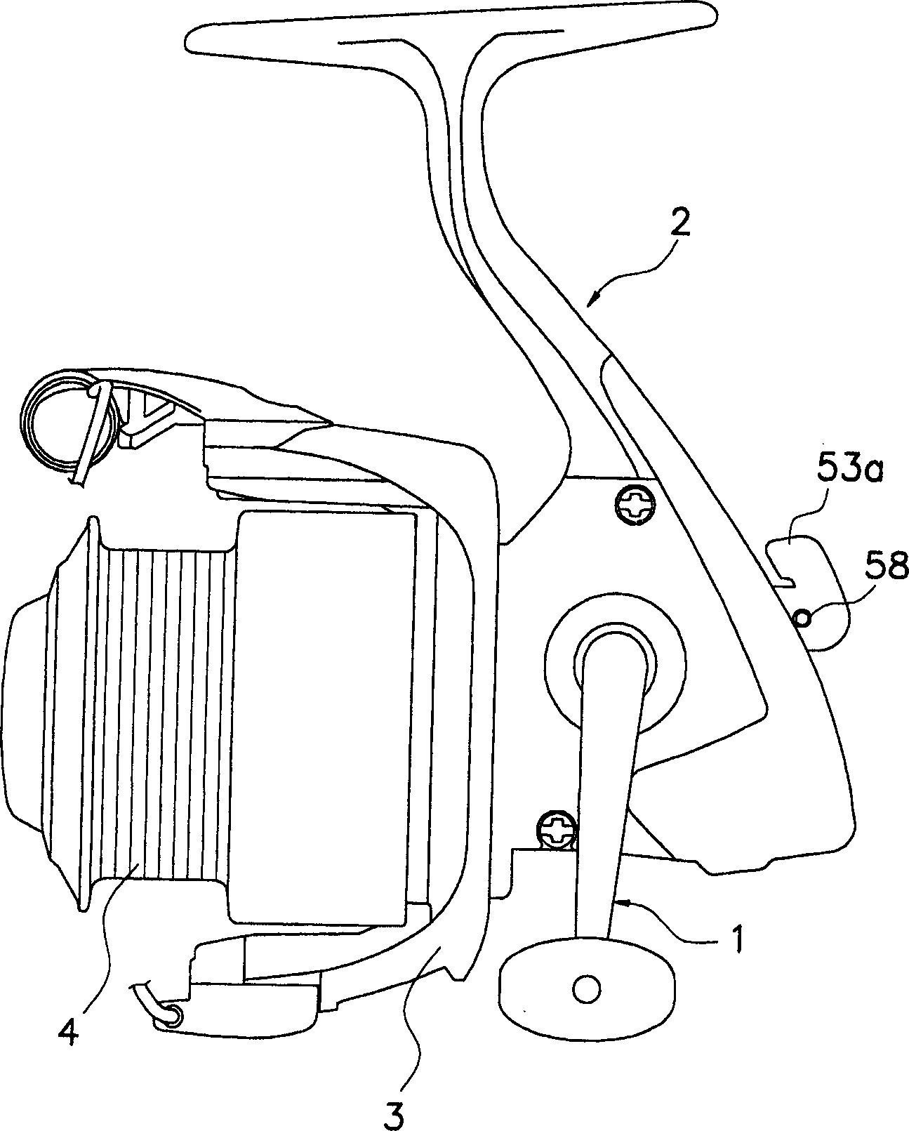
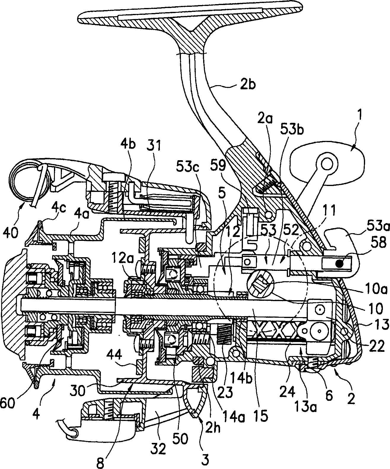
[0026] exist figure 1 Among them, a spinning reel according to an embodiment of the present invention has: a reel body 2 that can be mounted on a fishing rod, and a handle assembly that can be freely rotated around the left and right shafts 1. The rotor 3 and the reel 4. The rotor 3 rotates in conjunction with the rotation of the handle assembly 1, guides the fishing line into the spool 4, and is supported on the front portion of the reel body 2 so as to be rotatable around the front and rear axes. The spool 4 is arranged on the front portion of the rotor 3 so that the fishing line guided by the rotor 3 can be reciprocated freely in the front-rear axis direction on the outer peripheral surface.

[0027] Structure of the cord reel body

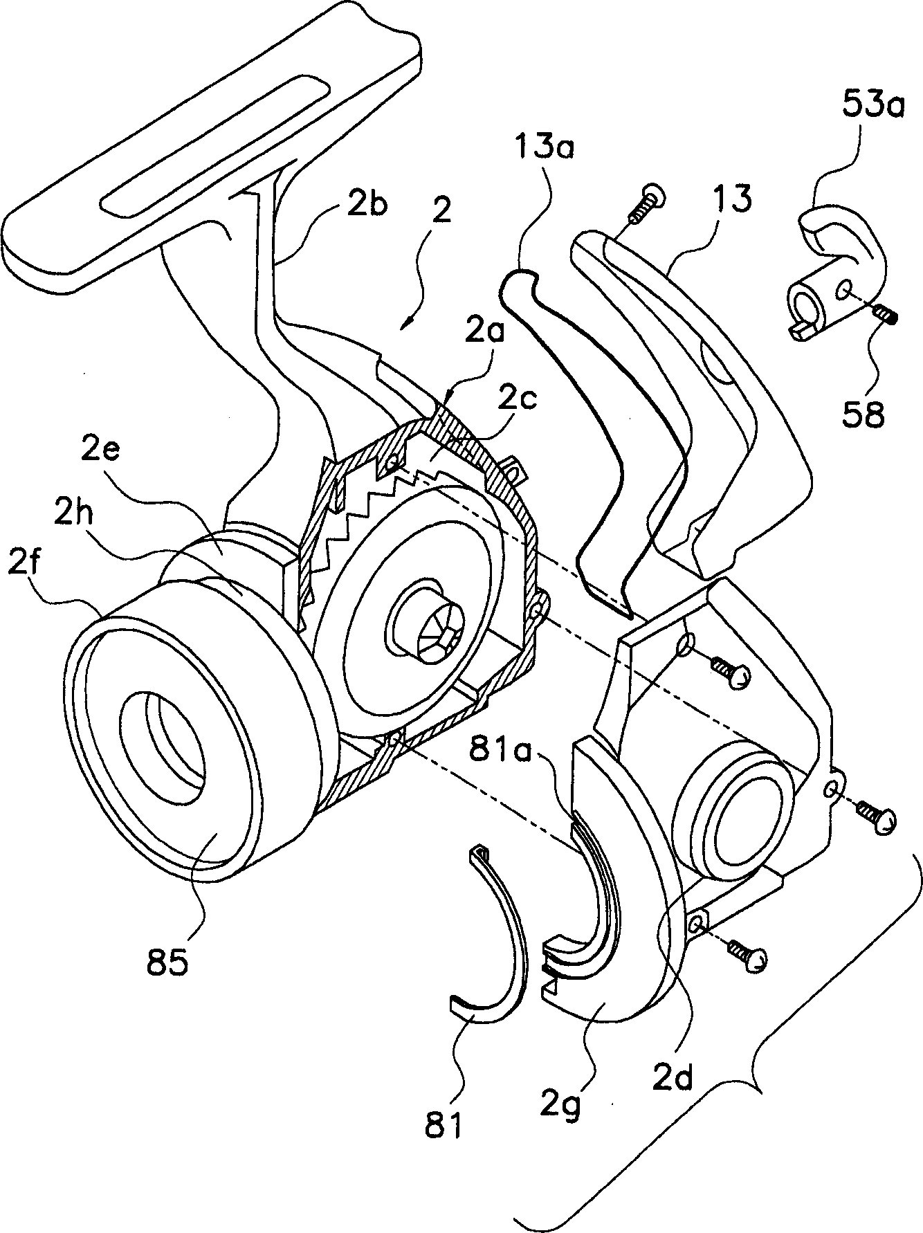
[0028] The cord reel body 2 such as image 3 As shown, there are: a cord reel housing 2a constituting the main part of the cord reel body 2 and having an opening 2c at the side; A cover member 2d is bolted to the...


PUM


Abstract

The present invention relates to a rotor of a spinning reel which, even designed to be lightweight, can be utilized in both situations where the rotational feel is a priority, and where powering efficiency is a priority. The solution of the present invention is a spinning reel rotor 3 that is rotatably mounted on a reel unit of a spinning reel 2 for winding a fishing line onto a spool 4. The rotor includes a rotor unit 8, a bail arm 40, and a ring 44. The rotor unit 8 has a cylindrical portion 30 that is rotatably mounted on a reel unit 2, and first and second rotor arms 31, 32 that extend forward from the rear edge of the cylindrical portion 30. The bail arm 40 guides the fishing line onto the spool 4 that is pivotably mounted on the front tips of both arms 31, 32. The ring 44 is a member for providing inertia and is detachably mounted on the rotor unit 8.

Description

technical field [0001] The invention relates to a rotor, in particular to a rotor of a spinning reel which is rotatably installed on the reel body of the spinning reel for winding fishing line on a reel for winding the line. Background technique [0002] Generally, a spinning reel has: a reel body mounted on a fishing rod; The rotor on the reel body that winds the fishing line onto the spool. The rotor has: a cylindrical part arranged on the inner peripheral side of the reel, first and second arm parts extending forward from the rear end of the cylindrical part, and swingably mounted on the tips of the two arm parts. , The guide ring arm that winds the fishing line on the spool. [0003] Recently, the rotor of such a spinning reel has been made of light metal such as aluminum alloy or magnesium alloy to reduce the weight. [0004] In conventional rotors that have been reduced in weight, in order to reduce the moment of inertia, the rotor is lightly started to rotate at th...

Claims


Application Information

Patent Timeline
Patent Type & Authority Applications(China)
IPC IPC(8): A01K89/01
CPCA01K89/0108A01K89/01
Inventor 菅原谦一
Owner SHIMANO INC
Why Eureka
Try Eureka