Chain tool container

A tool and chain technology, applied in the field of automatic tool changing devices, can solve problems such as large number of parts

Active Publication Date: 2014-10-15
TSUBAKIMOTO CHAIN CO
View PDF6 Cites 3 Cited by
  • Summary
  • Abstract
  • Description
  • Claims
  • Application Information

AI Technical Summary

Problems solved by technology

[0014] However, the above-mentioned existing chain tool barrels 700A-700C adopt a structure in which the tool holding units 720A-720C and the hollow pin shafts 710A-710C are relatively fixed by a spring pin (spring pin) 760, so there is the following maintenance: The above problem: not only the tool holding unit 720A~720C must be replaced, but also the hollow pin shaft 710A~710C must be replaced and the chain disassembled to correspond to tools TA~TC of different specifications; it is necessary to replace tools TA~TC of different specifications The number of parts is large; or, when the tool holding units 720A-720C are damaged, a complete set of tool barrels must be replaced

Method used


Image

  • Chain tool container
  • Chain tool container
  • Chain tool container

Examples


Embodiment

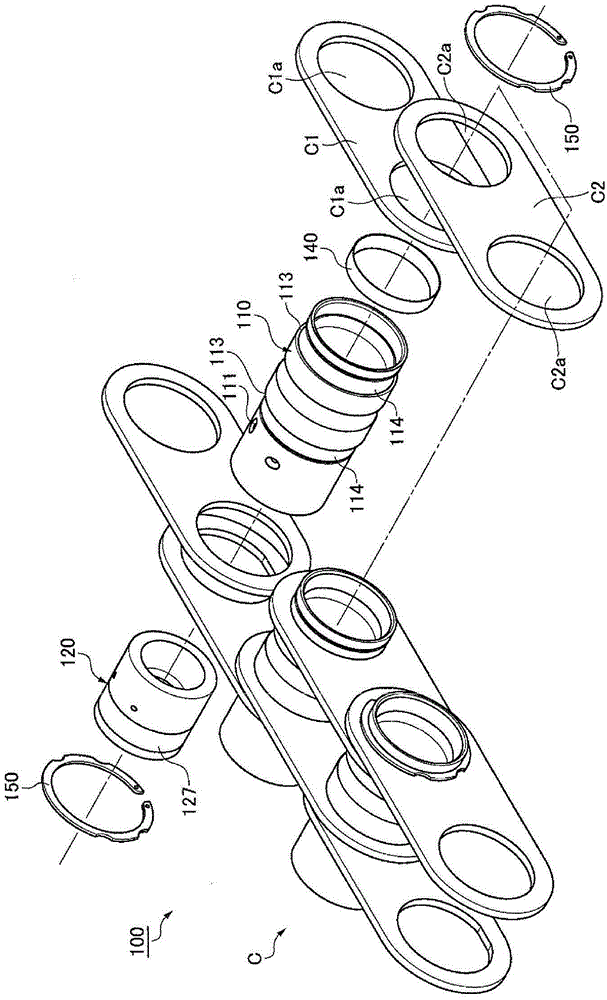
[0080] Below, refer to Figure 1 to Figure 5(C) , FIG. 5(B), and FIG. 5(C) to illustrate an embodiment of the present invention, that is, a tool holder 100 for a chain.

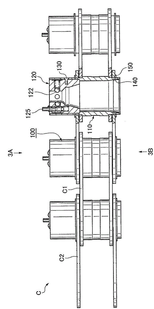
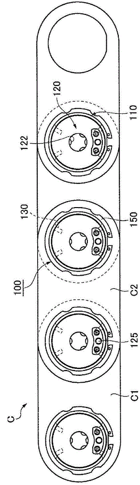
[0081] The embodiment of the present invention is that the tool barrel 100 for the chain is as Figure 1 to Figure 3(A) , as shown in FIG. 3(B), a tool holding unit 120 is provided, and the tool holding unit 120 holds the tool T detachably inside cylindrical hollow pin shafts 110, and the cylindrical hollow pin shafts 110 alternately A pair of inner panels C1 and a pair of outer panels C2 are connected.

[0082] Specifically, the chain C has: a pair of inner plates C1 spaced apart in the left and right width direction relative to the chain length direction; a pair of outer plates C2 arranged on the left and right outer sides of the pair of inner plates C1; and a hollow pin 110 .

[0083] Both sides of the hollow pin 110 are inserted through the insertion hole C1a of the inner panel C1 and the insertion hol...


PUM


Abstract

A chain tool container corresponds to tools of different standards without detachment of a hollow bolts from inner plates and outer plates, and reduces a number of components that are required for replacing a tool of another standard, when compared with a structure, in which an entire canister set is replaced. In the chain tool container, a tool holding units are detachable with respect to the hollow bolts, and a plurality of tool holding units of various type are provided corresponding to tools of different standards. The outer diameter of each tool holding unit is consistent with the tools of corresponding standard. The position of a retaining means in an axial direction of the tool holding unit varies according to the different standard of a tool. The predetermined location on the tool holding unit side is aligned with a predetermined location on hollow bolt side, so as to installed the tool holding unit at a predetermined position within the hollow bolt.

Description

technical field [0001] The present invention relates to a tool pot for a chain used in an automatic tool changer equipped in a machine tool such as a machining center. Background technique [0002] Conventionally, there is known a tool barrel for chains, which is equipped with a tool holding unit (unit) that holds a tool detachably inside a cylindrical hollow pin (hollow pin). A pair of hollow pins alternately connect a pair of inner plates (plate) and a pair of outer plates (for example, refer to Patent Document 1). [0003] As such an existing tool box for chains, for example, there are Figure 6(A) to Figure 6(C) Chain tool barrels 700A to 700C are shown. [0004] Here, FIG. 6(A) is a planar cross-sectional view showing a conventional tool holder 700A for a chain that can freely hold a tool TA of the MAS standard, and FIG. 6(C) is a planar cross-sectional view showing a conventional tool barrel 700C for a chain that can freely hold a tool TC of the DIN standard. [000...

Claims


Application Information

Patent Timeline
Patent Type & Authority Applications(China)
IPC IPC(8): B23Q3/155
CPCB23Q3/157B23Q3/15526B23Q3/1572B23Q3/15724B23Q2003/15527
Inventor 小山智之
Owner TSUBAKIMOTO CHAIN CO
Why Eureka
Try Eureka