Subscriber station with duplex antenna amplifier

An antenna amplifier and mobile station technology, applied in the field of signal devices, can solve problems such as economic reduction

Inactive Publication Date: 2002-08-21
JSC KODOFON
View PDF2 Cites 7 Cited by
  • Summary
  • Abstract
  • Description
  • Claims
  • Application Information

AI Technical Summary

Problems solved by technology

Since the power amplifier 11 is always on, and its energy consumption far exceeds the energy consumption of the MS in passive mode, the economical efficiency of this user equipment including the MS, the antenna amplifier and the antenna is greatly reduced.

Method used


Image

  • Subscriber station with duplex antenna amplifier
  • Subscriber station with duplex antenna amplifier
  • Subscriber station with duplex antenna amplifier

Examples


Embodiment Construction

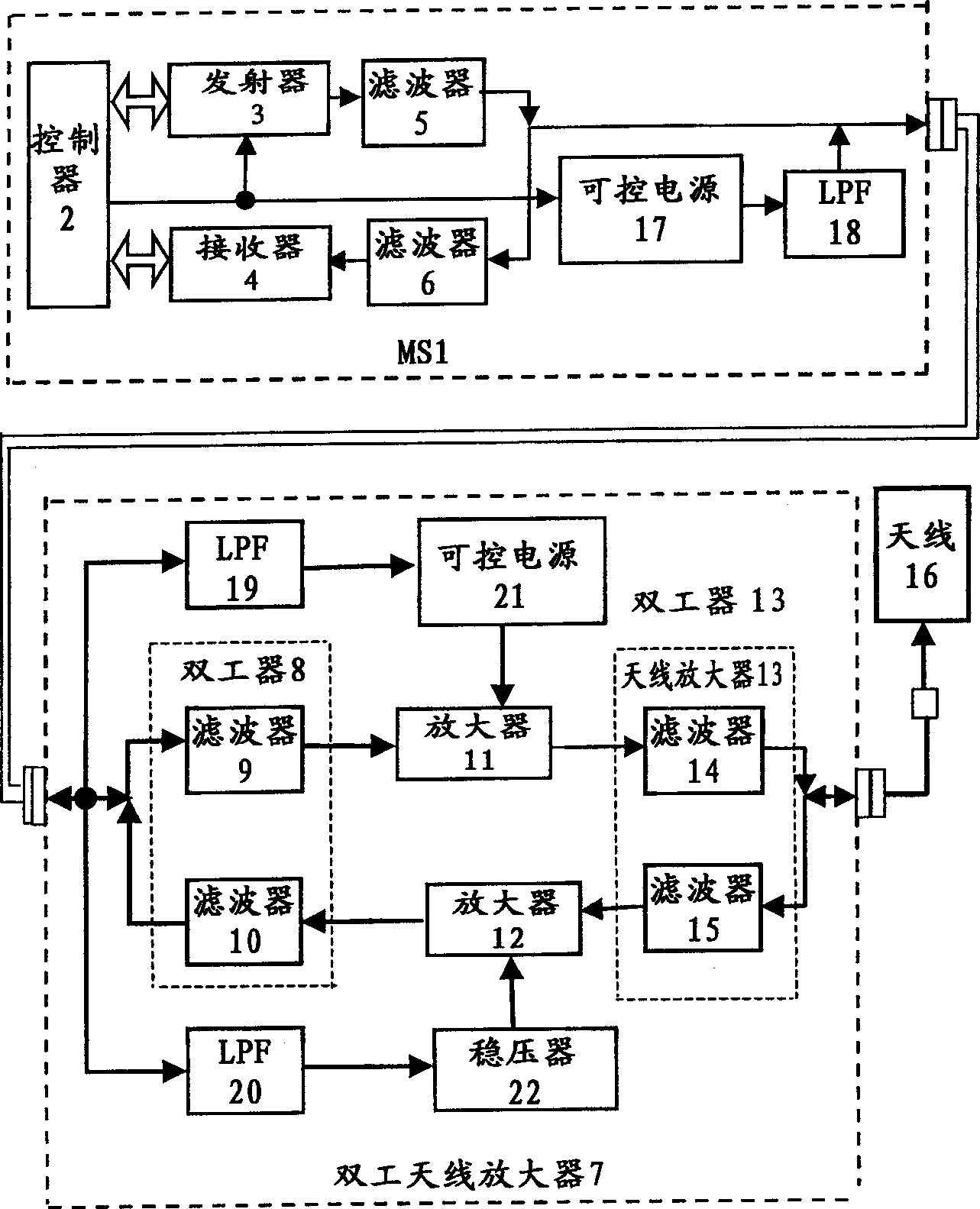
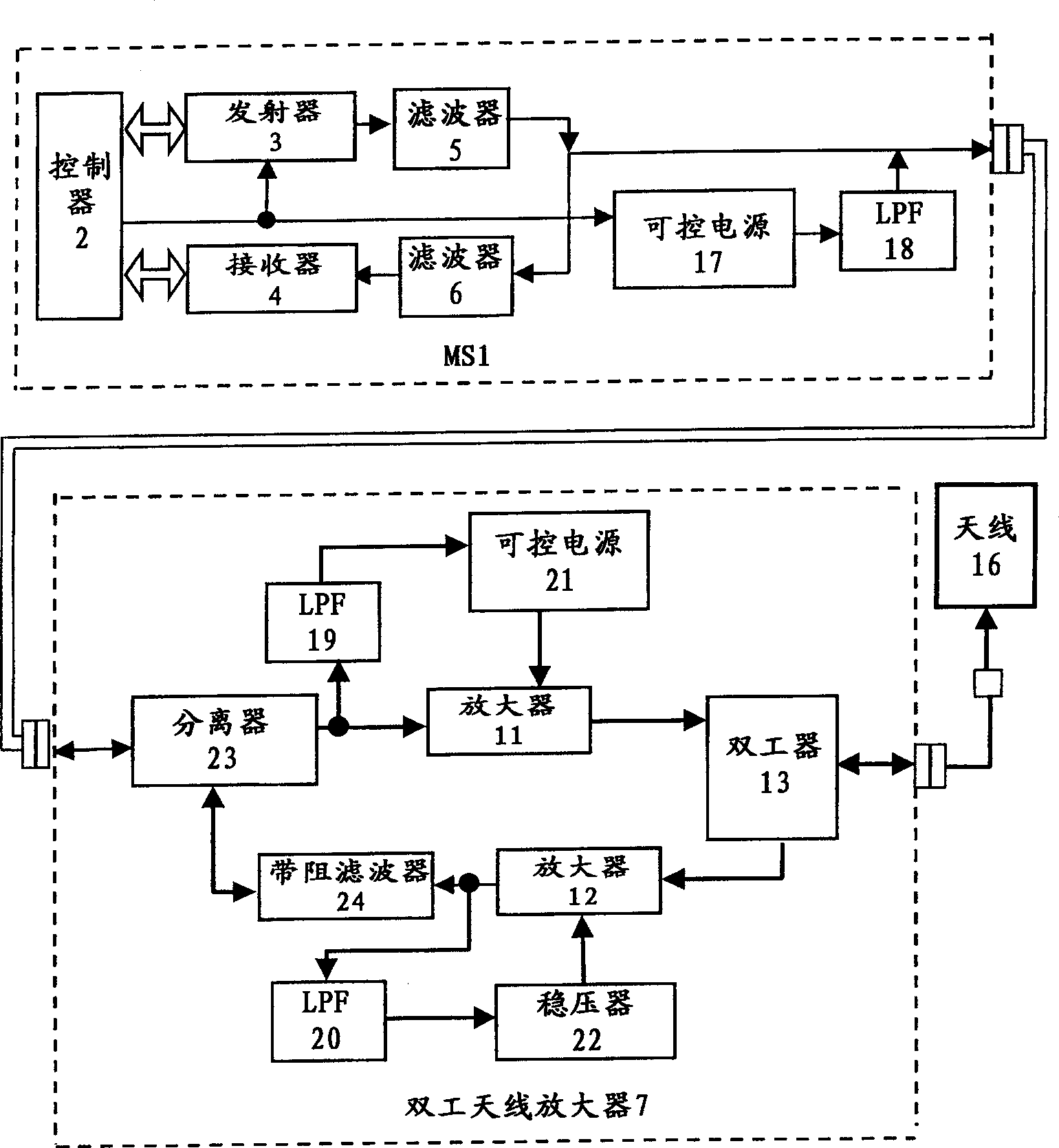
[0031] The block diagram of the first modification of the device proposed by the present invention is as figure 2 shown.

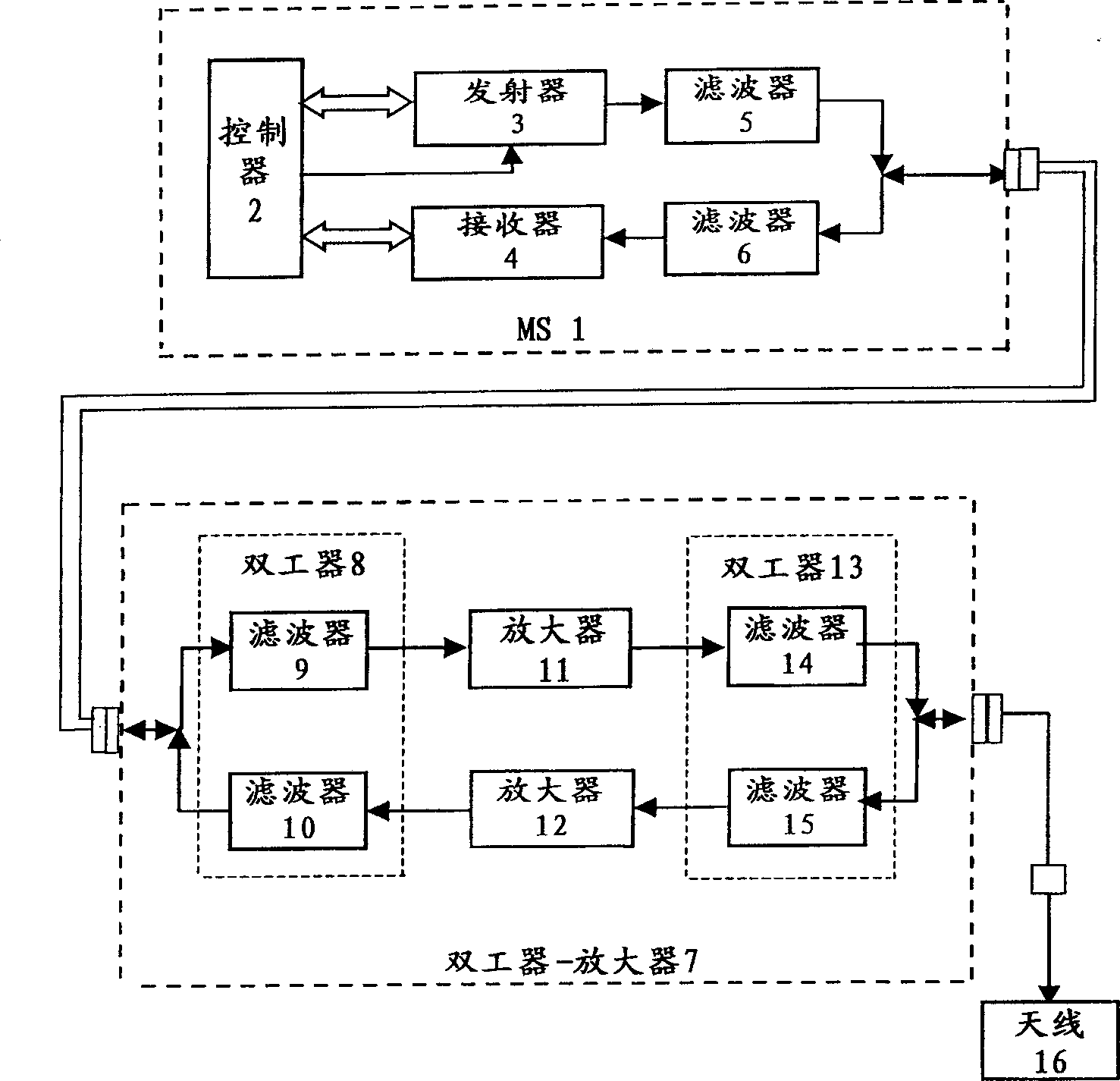
[0032] This user equipment consists of an MS connected by a communication line and a duplex antenna amplifier 7 to which an antenna 16 is connected.

[0033] According to the invention, MS1 comprises a controller 2, the input / output of which is connected to the output / input of transmitter 3 and receiver 4, the output of transmitter 3 is connected to the MS1 via a first filter 5. Output / input, the input of the receiver 4 is connected to the input / output of MS1 via a second filter 6 . The control output of the controller 2 is connected to the control input of the transmitter 3 . Furthermore, a controllable power supply 17 whose input is connected to the control output of the controller 2 is introduced into the MS. The output terminal of the controllable power supply 17 is connected to the output / input terminal of MS1 through the first LPF18.

[0034] Ac...


PUM


Abstract

According to the invention, in order to make a system more economical during full compensation of the attenuation of a transmitter and receiver signal in a communication cable, a subscriber station includes a transmitter on / off control circuit with a controlled power source (a control command converter) and a low-pass filter used to separate a transmission / reception VHF signal from a lower frequency (up to a D.C. level) control signal / command, whereby the power supply of the subscriber station is autonomous. In the first variant of the inventive device, a control command passing through the low-pass filter 19 turns on the control of the power source 21 supplying the power amplifier 11. The amplification is selected to compensate for the attenuation of the transmitter signal on its way from the subscriber station 1 to the antenna 16. By means of an interconnect cable, the supply voltage from the subscriber station is fed into a stabilizer 22 through another low-pass filter 20 which performs decoupling of the supply circuit from the transmission and reception radiofrequency signals. In the second variant of the device, the duplex antenna amplifier 7 includes a splitter and a rejector filter 24, which enables the simplification of the design of the antenna amplifier and makes it less expensive.

Description

Technical field: [0001] The present invention relates to radio technology, in particular to a device for amplifying signals transmitted in all directions in a common frequency band (common frequency band) through radio communication lines, and the device can be applied to radio transmission systems such as cellular communication systems . Background technique: [0002] Designers of radio devices in the higher frequency range have encountered the problem of signal loss in radio transmission lines connected to antennas and transceiver equipment. The loss of transmitting high-frequency signals with coaxial communication cables is small, but the cost is very expensive. Nevertheless, if the transmission distance is quite long, there will still be a loss of 20dB or more. The result is often reduced performance of the signal. In practice, antenna amplifiers are used to control the power input to the antenna and to compensate for attenuation of the radio signal in the transmissio...

Claims


Application Information

Patent Timeline
Patent Type & Authority Applications(China)
IPC IPC(8): H04B1/38H04B1/52H04B3/06H04B3/36H04L5/14
CPCH04B3/06H04B1/52H04B1/3877
Inventor 亚历山大·V·加尔莫诺夫S·N·多季克A·M·热列布季耶夫Y·V·格里休克
Owner JSC KODOFON
Why Eureka
Try Eureka