

Method and equipment for producing a printing block
A printing block and equipment technology, applied in printing, printing plate preparation, welding equipment, etc., can solve the problem of not being able to produce fine and simultaneous low-level areas, and achieve the effect of good quality and precise operation
- Summary
- Abstract
- Description
- Claims
- Application Information
AI Technical Summary
Problems solved by technology
Method used
Image

Examples
Embodiment Construction
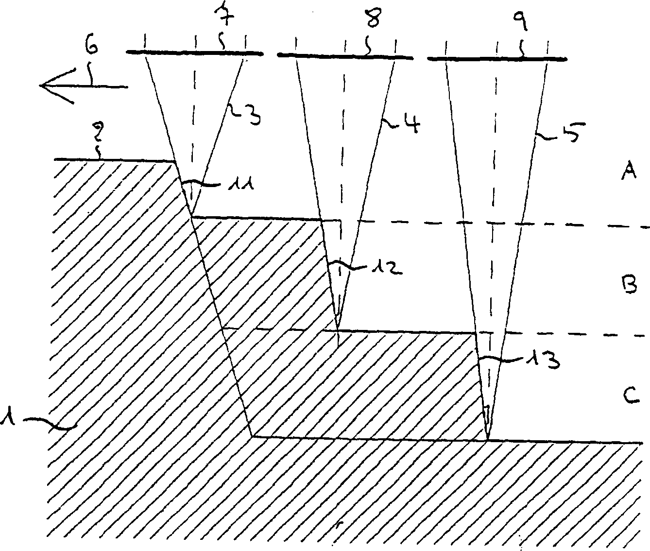
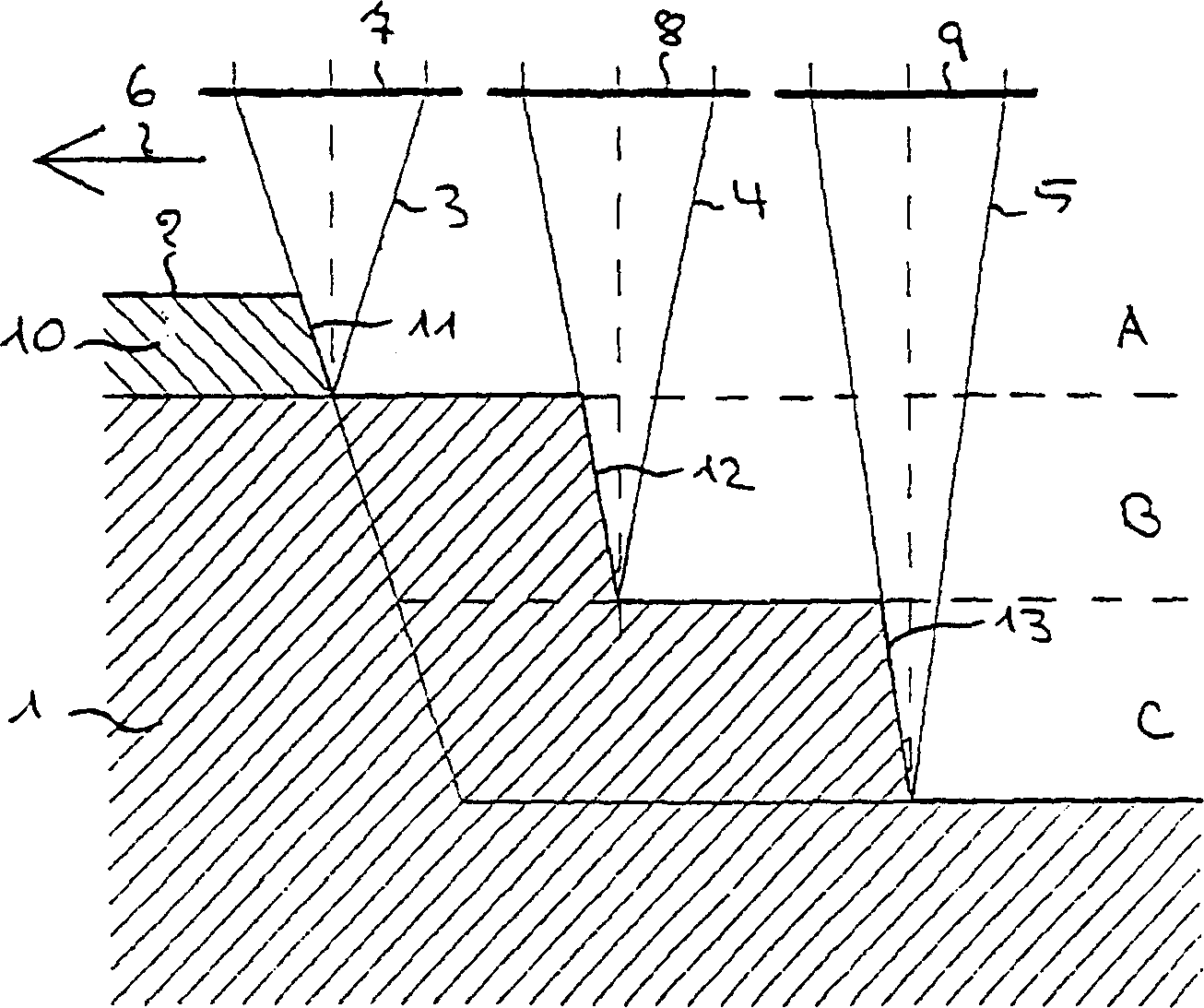
[0049] The following reference figure 1 The principle of operation in the present invention is explained in more detail. exist figure 1 , reference numeral 1 designates a printing block blank produced from polymeric material. For example to produce an offset printing block, a relief is etched on the surface 2 of the printing block blank 1 by burning away areas of polymeric material on the printing block blank 1 by means of eg three focused laser beams 3, 4 and 5. More or less than three laser beams can be used. For this purpose, the laser beams 3 , 4 and 5 are continuously moved along a trajectory running on the surface 2 in the direction of the arrow 6 . The laser beam 3 is the main laser beam and first of all acts on the surface 2 of the printing block blank 1 . It is followed by the laser beam 4 following a time delay along the same track, which is likewise followed by the laser beam 5 following a time delay along the same track. Depending on the depth of a recess to b...
PUM
 Abstract
Description
Claims
Application Information